Audi A6 Typ 4G: Hill Start
Hill Start, System Description
The vehicle may be equipped with hill start depending on the model.
Function
The function assists the driver if the vehicle must stop frequently or for long periods of time while the engine is running.
The hill start holds the vehicle after the vehicle has been stationary and this function is activated.
The driver can release the brake pedal.
The vehicle is held in place by maintaining the brake pressure on all four wheels in ESP.
To prevent the ESP solenoid valves from overheating when stopped for long periods of time, the electromechanical parking brake automatically assumes braking when the solenoid valves reach a temperature of 200 ºC (392 ºF).
The point when the brakes automatically release is based on the following factors:
- Engine speed
- Angle
- Gear engaged
- On manual transmissions, clutch pedal travel per the clutch sensor
- On automatic transmissions, through converter release
To prevent the vehicle from rolling back, the brakes are only released when there is sufficient engine torque available.
Activation
The following conditions must be fulfilled to switch the "stand by" function on:
- Driver wearing seat belt
- Engine running
- Driver door closed
- ESP and electromechanical parking brake are not malfunctioning.
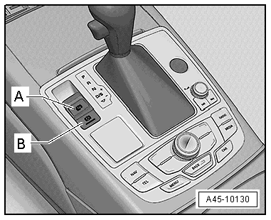
Pressing the -AUTO HOLD- Button -E540--B- in the center console activates this function.
The switch indicates the operating conditions.
- Deactivated - the LED in the switch is off.
- Stand by - the LED inside the switch is on.
- Active - the LED in the switch is on and the instrument cluster display shows a green "P".
Braking function is only transferred from ESP to the electromechanical parking brake if the "green P" in the instrument cluster is on and if:
- the solenoid valves in ESP have reached a temperature of 200 ºC (392 ºF)
- the driver door is opened
- the driver seat belt is unbuckled
- the engine is stopped
- the ignition is switched off
- the brake pedal or gas pedal is pressed.
- The -AUTO HOLD- Button -E540- was pressed without pressing the brake pedal.
 Note
Note
When braking function is transferred from the ESP to the electromechanical parking brake, the display in the instrument cluster changes from a "green P" to a "red P".
Special Tools
Special tools and workshop equipment required
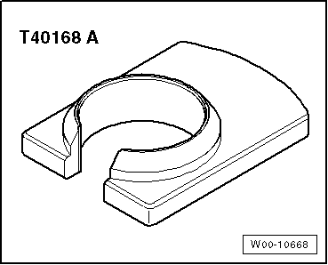
- Release Tool for Brake Light Switch -T40168A-
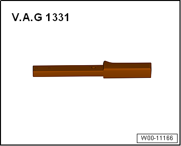
- Torque Wrench 1331 5-50Nm -VAG1331-
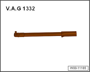
- Torque Wrench 1332 40-200Nm -VAG1332-
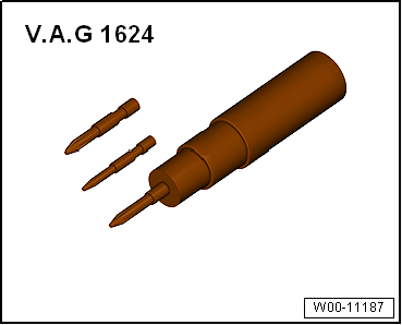
- Torque Screwdriver -VAG1624-
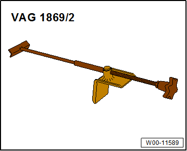
- Brake Pedal Actuator -VAG1869/2-.
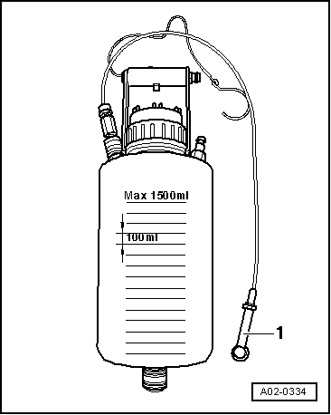
- Brake Charger/Bleeder Unit -VAS5234-
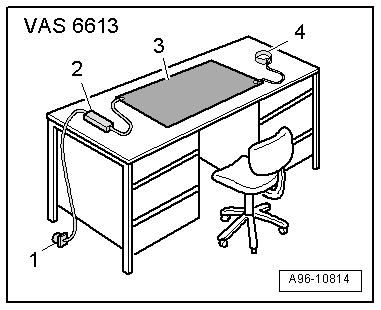
- ESD Work Surface -VAS6613-
- Assembly Part Set -5Q0698311-
