Audi A6 Typ 4G: CV Joint, Servicing
Outer CV Joint, Removing
- Clamp the drive axle with protective jaws in a vise clamp.
- Open both clamping sleeves and remove protective joint boot from outer joint.
- Strike a copper or brass drift -A- on CV joint inner race with a hammer.
- Remove joint and protective joint boot.
Outer CV Joint, Installing
Joints and protective joint boots must be free of grease.
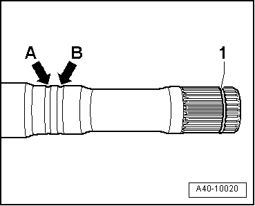
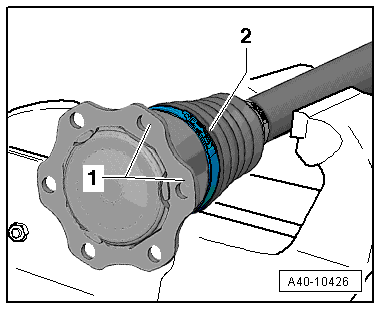
- Replace the circlip -1-.
- Slide on the small clamp with the CV boot and position the CV boot on the drive axle.
- Position CV boot in outer groove -arrow B-.
Inner groove -arrow A- remains visible "identification groove" (for correct installation of CV boot).
- Add the specified quantity of grease to the inner joint.
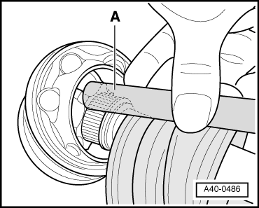
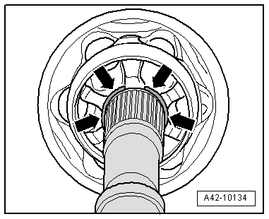
- Before installing joint piece, splines -A- must be lightly coated with grease used in joint.
- Insert sealing ring in groove on shaft.
- Slide on CV joint up to sealing ring.
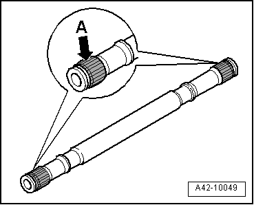
- Align sealing ring at center with opening upward -see arrows-.
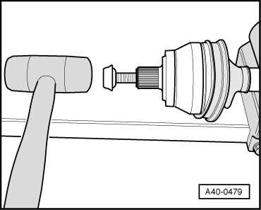
- Screw old drive axle bolt into joint as shown in the illustration.
- Drive joint onto drive axle with plastic hammer until circlip engages.
- Add the specified quantity of grease to the inner joint.
- Slide the protective boot onto the joint.
- Bleed protective joint boot.
- Make sure the protective boot is seated on the joint correctly.
- Protective joint boot must fit in groove and on joint contour.
- Tension the clamps on outer joint. Refer to → Chapter "Clamp on Triple Roller Joint and Outer Joint, Tensioning".
Outer CV Joint, Checking
It is necessary to disassemble the joint whenever replacing the grease or if the ball surfaces show wear or damage.
 Note
Note
Ball hub and joint are paired and should be identified before removal. Do not interchange cage allocation.
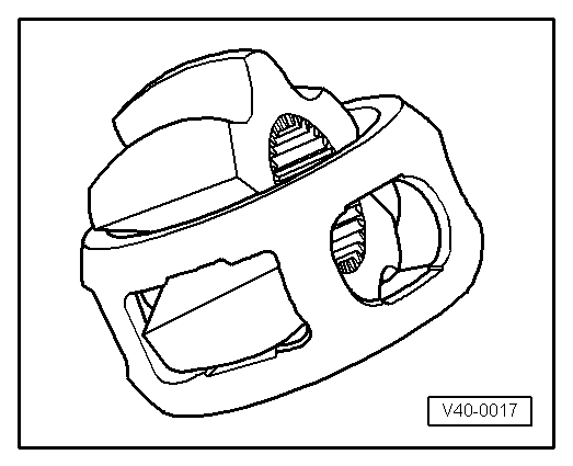
Disassembling
- Mark position of ball hub to ball cage and to housing before disassembling, using electro-writer or grindstone.
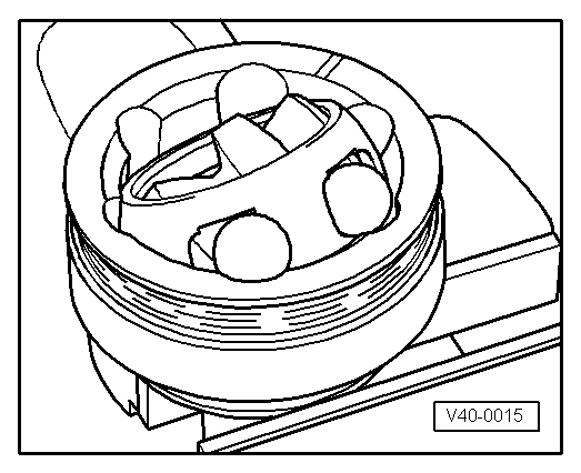
- Swivel the ball hub and ball cage.
- Remove the balls one after the other.
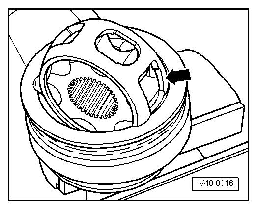
- Turn cage, until two rectangular windows -arrow- contact joint body.
- Lift out cage with hub.
- Swing hub segment with smaller pins into rectangular window on cage.
- Fold hub out from cage.
Checking
The balls of each joint belong to one tolerance group. Check stub axle, hub, cage and balls for small depressions (pitting build-up) and chafing. Excessive circumferential backlash in joint makes itself noticed via tip-in shock, in such cases joint should be replaced. Flattening and running marks of balls are no reason to replace joint.
Assembling
- Insert cage with hub into joint body.
Note
- Be sure to install each individual part into the its original position when assembling the joint.
- Cage must be installed laterally correct.
- Press in opposing balls in sequence, during this, previous position of ball hub to ball cage and to joint body must be established again.
- Press the grease into the joint body.
Clamp on Triple Roller Joint and Outer Joint, Tensioning
Depending on the version of the clamp, use the following tools:
Special tools and workshop equipment required
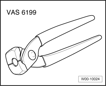
- Locking Pliers -VAS6199-
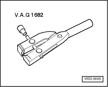
- Clamping Pliers -VAG1682A-
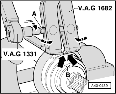
Mount and Tension Stainless Steel Clamps Using Clamping Pliers -VAG1682A- as Illustrated.
- Make sure that the jaws of the tension clamp seat in the corners -arrows B- of the connecting tube.
- Tighten the clamp by turning the spindle using a torque wrench -C- (do not tilt the pliers).
- The hard material of the CV boot (compared to rubber) makes it necessary to use a stainless steel hose clamp. It is only possible to tighten the hose clamp with Clamping Pliers -VAG1682A-.
- Tightening specification: 20 Nm.
- Use torque wrench with 5 to 50 Nm range (for example, Torque Wrench 1331 5-50Nm -VAG1331-).
- Make sure the thread on the spindle -A- is easy to move. Lubricate with MoS2 grease, if necessary.
- If the thread is tight, for example, dirty, the required tensioning force for the hose clamp will not be achieved in spite of correct torque specification settings.
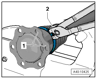
Attach and Tension the Clamp with the Tabs Using the Locking Pliers -VAS6199-, as illustrated.
- For a better alignment of multi-point socket head bolts when installing drive axle, the lock -2- on the clamping sleeve must be located between the joint connecting flanges -1-.
- Engage the clamp at the first catch by hand.
- Close the clamp using the Locking Pliers -VAS6199--2-.
Special Tools
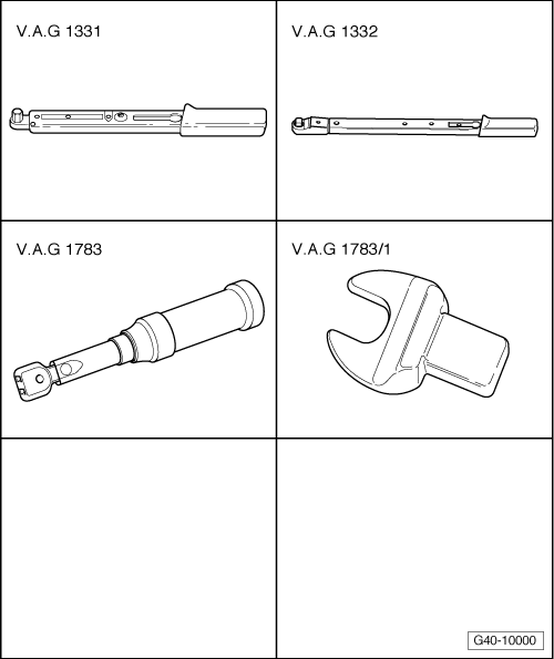
Special tools and workshop equipment required
- Torque Wrench 1331 5-50Nm -VAG1331-
- Torque Wrench 1332 40-200Nm -VAG1332-
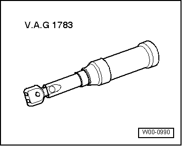
- Torque Wrench 1783 - 2-10Nm -VAG1783-
- Torque Wrench 1783 - Open Jaw - 10mm -VAG1783/1-
- Wood block (hardwood) 30 x 50 x 1000 mm
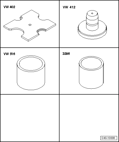
- Press Plate -VW402-
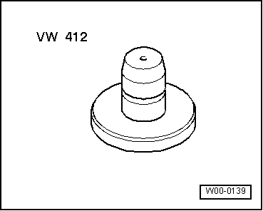
- Press Piece - Multiple Use -VW412-
- Press Piece - 42mm -VW516-
- Press Piece - Reverse Gear Syncro - 3296-
- Assembly Paste -G 052 109 A2-
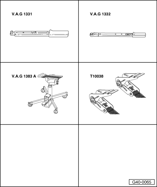
- Torque Wrench 1331 5-50Nm -VAG1331-
- Torque Wrench 1332 40-200Nm -VAG1332-
- Engine and Gearbox Jack -VAS6931-
- Tensioning Strap -T10038-, quantity: 2
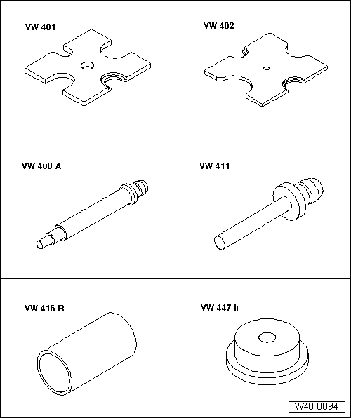
- Press Plate -VW401-
- Press Plate -VW402-
- Press Piece - Rod -VW408A-
- Press Piece - Rod -VW411-
- Press Piece - 37mm -VW416B-
- Press Piece - Multiple Use -VW447H-
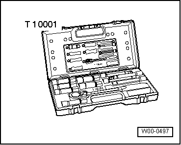
- Shock Absorber Set -T10001-
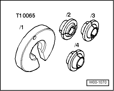
- Tripod Joint Tool -T10065-
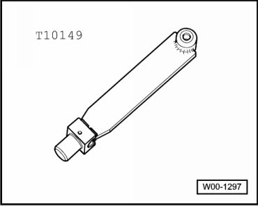
- Engine/Gearbox Jack Adapter - Wheel Hub Support -T10149-
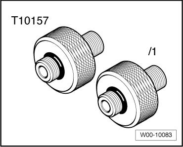
- Air Spring Strut Adapter -T10157-
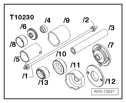
- Hydraulic Press - Bushing Assembly Tool Kit -T10230-
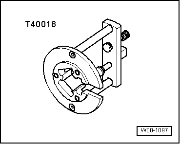
- Triple Roller Assembly Tool -T40018- for triple roller joint AAR 3300 i
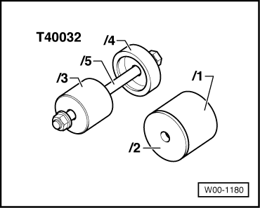
- Puller - Differential Bearing -T40032-
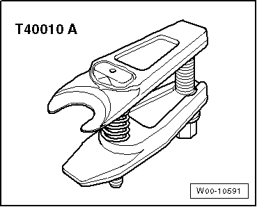
- Puller - Ball Joint -T40010A-
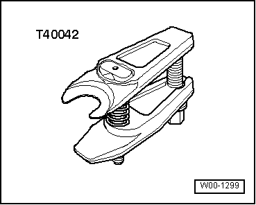
- Puller - Ball Joint -T40042-
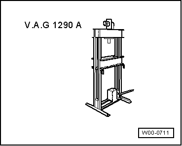
- Shop Press -VAG1290A-
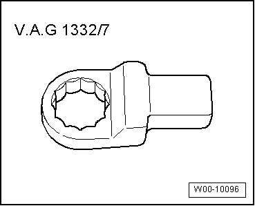
- Torque Wrench 1332 Insert - Ring Wrench - 21mm -VAG1332/7-
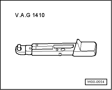
- Torque Wrench 1410 -VAG1410-
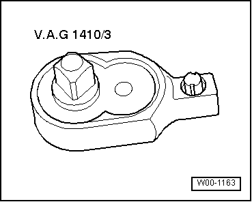
- Torque Wrench 1410 Insert - Ratchet -VAG1410/3-
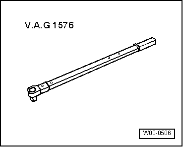
- Torque Wrench 80-400Nm -VAG1576-
- Clamping Pliers -VAG1682A-
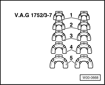
- Spring Compressor Kit - Spring Tensioner -VAG1752/1-
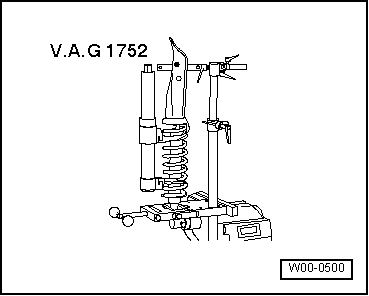
- Spring Compressor Kit - Spring Retainer w/Inserts -VAG1752/6-
- Torque Wrench 1783 - 2-10Nm -VAG1783-
- Locking Pliers -VAS6199-
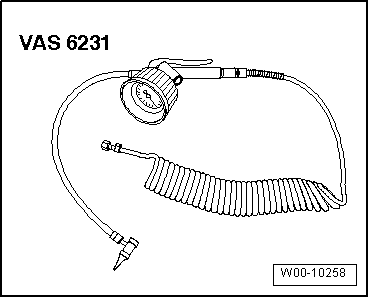
- Air Suspension Strut Charger -VAS6231-
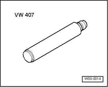
- Press Piece - Rod -VW407-
- Press Piece - Multiple Use -VW412-
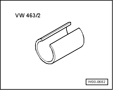
- Press Piece - Split Tube -VW463/2-
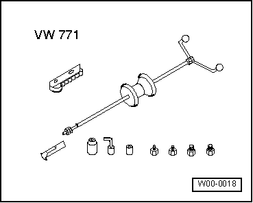
- Slide Hammer Set -VW771-
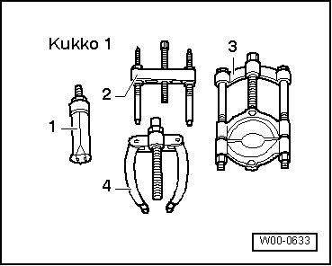
- -3-Puller - Kukko Separating Tool - Diameter 25-155mm with Puller - Kukko Quick Action Separating Tool - 25-155mm -15/3 with 17/3-
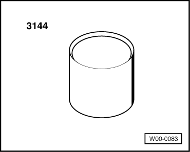
- Bearing Installer - Wheel Bearing -3144-
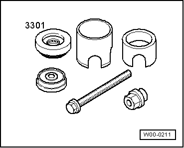
- Subframe Bushing Tool Kit -3301-
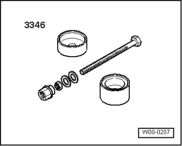
- Bearing Installer - Control Arm -3346-
- Bearing Installer - Multiple Use -3348-
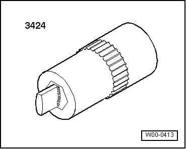
- Spreader Tool -3424-
- Torque Wrench 1331 Insert - Ring Wrench - 16mm -VAG1331/12-
- For a vehicle with air suspension Vehicle Diagnostic Tester