Audi A6 Typ 4G: Overview - Rear Axle, Overview - Subframe
Overview - Rear Axle
Part I
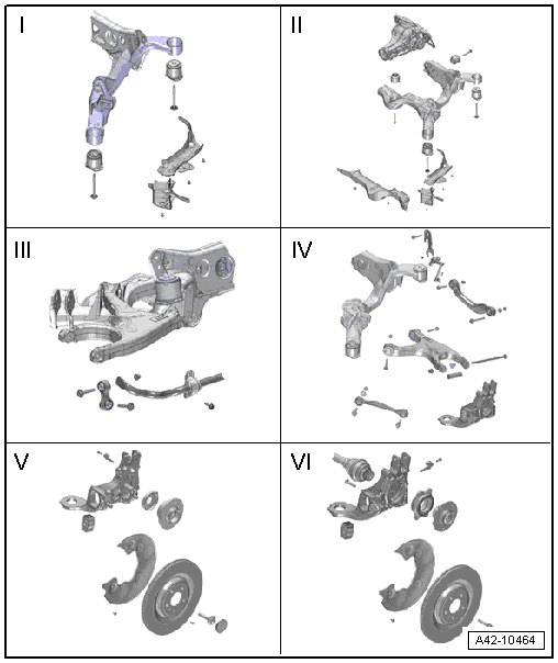
I - → Chapter "Overview - Subframe, Vehicles with FWD"
II - → Chapter "Overview - Subframe, Vehicles with AWD"
III - → Chapter "Overview - Stabilizer Bar"
IV - → Chapter "Overview - Transverse Link"
V - → Chapter "Overview - Wheel Bearing, Vehicles with FWD"
VI - → Chapter "Overview - Wheel Bearing Housing, Vehicles with AWD"
Part II
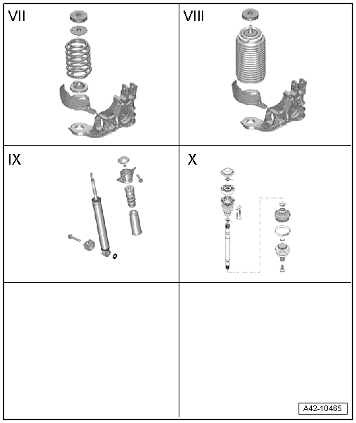
VII - → Chapter "Overview - Suspension Strut, Shock Absorber and Spring, Coil Spring"
VIII - → Chapter "Overview - Suspension Strut, Shock Absorber and Spring, Air Spring"
IX - → Chapter "Overview - Suspension Strut, Shock Absorber and Spring, Shock Absorber"
X - → Chapter "Overview - Drive Axle"
Overview - Subframe
Overview - Subframe, Vehicles with FWD
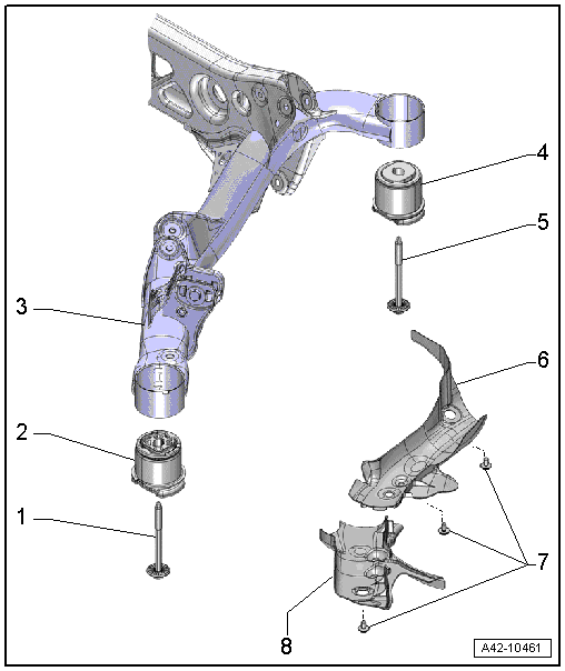
1 - Bolt
- 115 Nm +90º turn
- Always replace if removed
2 - Front Bonded Rubber Bushing
- for the subframe mounting
- There are different versions. Refer to → Fig. "Front and Rear Bonded Rubber Bushings". For the correct allocation. Refer to the Parts Catalog.
- Oil on the hydraulic bonded rubber bushing is a sign of wear.
- Replacing. Refer to → Chapter "Subframe Front Bearing, Replacing, Vehicles with FWD".
- Replace on both sides.
3 - Subframe
- Subframe with attachments, removing and installing. Refer to → Chapter "Subframe, Removing and Installing, FWD Vehicles".
- Subframe, securing. Refer to → Chapter "Subframe, Securing, FWD".
 Note
Note
An AWD subframe is installed for hybrid vehicles. For the correct allocation. Refer to the Parts Catalog. Performing repairs on the subframe is not affected.
4 - Rear Bonded Rubber Bushing
- For the subframe mounting
- There are different versions. Refer to → Fig. "Front and Rear Bonded Rubber Bushings". For the correct allocation. Refer to the Parts Catalog.
- Oil on the hydraulic bonded rubber bushing is a sign of wear.
- Replacing. Refer to → Chapter "Subframe Rear Bearing, Replacing, Vehicles with FWD".
- Replace on both sides.
5 - Bolt
- 115 Nm +90º turn
- Always replace if removed
6 - Rear Stone Chip Protection
- Depending on the date of manufacture
7 - Clip
- Depending on the date of manufacture
8 - Front Stone Chip Protection
- Depending on the date of manufacture
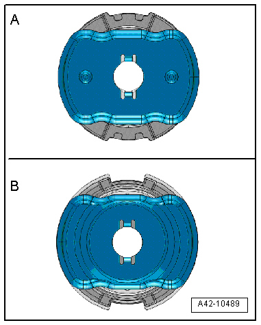
Front and Rear Bonded Rubber Bushings
A - Hydraulic bonded rubber bushing
B - Conventional bonded rubber bushing
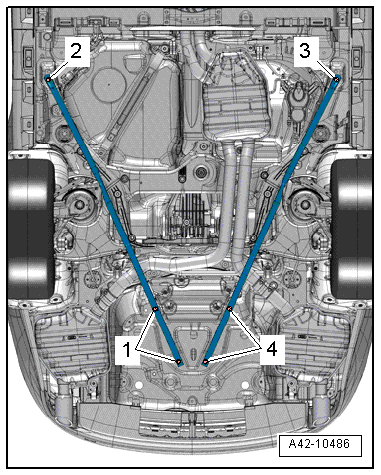
Diagonal Brace - Tightening Specification
 Note
Note
Replace the bolts that were tightened with an additional turn.
- Tighten the bolts -1 through 4- to 50 Nm +90º turn.
Overview - Subframe, Vehicles with AWD
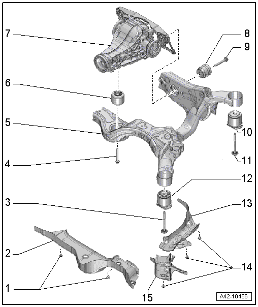
1 - Clip
- Depending on the date of manufacture
2 - Center Stone Chip Protection
- Depending on the date of manufacture
3 - Bolt
- 115 Nm + 90º turn
- Always replace if removed
4 - Bolt
- Tightening specification. Refer to → Rear Final Drive 0BC, 0BD, 0BE, 0BF; Rep. Gr.39.
5 - Subframe
- Subframe with attachments, removing and installing. Refer to → Chapter "Subframe, Removing and Installing, AWD Vehicles".
- Subframe, securing. Refer to → Chapter "Subframe, Securing, Vehicles with AWD".
6 - Front Bonded Rubber Bushing
- For the rear final drive mount
- Replacing. Refer to → Chapter "Rear Final Drive Front Bearing, Replacing, AWD Vehicles".
7 - Rear Final Drive
- Removing and installing. Refer to → Rear Final Drive 0BC, 0BD, 0BE, 0BF; Rep. Gr.39.
8 - Rear Bonded Rubber Bushing
- For the rear final drive mount
- Replacing. Refer to → Chapter "Rear Final Drive Rear Bearing, Replacing, AWD Vehicles".
9 - Bolt
- Tightening specification. Refer to → Rear Final Drive 0BC, 0BD, 0BE, 0BF; Rep. Gr.39.
10 - Rear Bonded Rubber Bushing
- For the subframe mounting
- There are different versions. Refer to → Fig. "Front and Rear Bonded Rubber Bushings". For the correct allocation. Refer to the Parts Catalog.
- Oil on the hydraulic bonded rubber bushing is a sign of wear.
- Replacing. Refer to → Chapter "Subframe Rear Bearing, Replacing, Vehicles with AWD".
- Always replace on both sides.
11 - Bolt
- 115 Nm + 90º turn
- Always replace if removed
12 - Front Bonded Rubber Bushing
- For The Subframe Mounting
- There are different versions. Refer to → Fig. "Front and Rear Bonded Rubber Bushings". For the correct allocation. Refer to the Parts Catalog.
- Oil on the hydraulic bonded rubber bushing is a sign of wear.
- Replacing. Refer to → Chapter "Subframe Front Bearing, Replacing, Vehicles with AWD".
- Always replace on both sides.
13 - Left Stone Chip Protection
- Depending on the date of manufacture
14 - Clip
- Depending on the date of manufacture
15 - Left Front Stone Chip Protection
- Depending on the date of manufacture
Front and Rear Bonded Rubber Bushings
A - Hydraulic bonded rubber bushing
B - Conventional bonded rubber bushing


