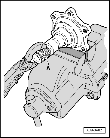
Audi A6 Typ 4G: Differential
Left Flange Shaft, Removing and Installing
Special tools and workshop equipment required
- Grease. Refer to the Parts Catalog.
Removing
- Secure the transmission on the Engine And Transmission Holder -VAS6095-. Refer to → Chapter "Securing on Engine and Transmission Holder".
- Tilt the transmission back on the engine/transmission holder so the transmission fluid does not drain out.
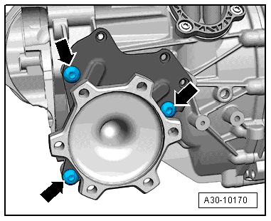
- Remove the bolts -arrows- from the flange shaft mounting bracket.
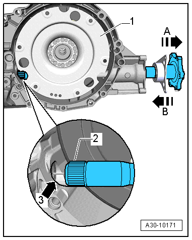
- Remove the left flange shaft -2- from the transmission in direction of -arrow A-.
 Note
Note
Ignore -1- and -arrow 3, B-.
- Remove the flywheel → Chapter "Flywheel, Removing and Installing".
Installing
Install in reverse order of removal. Note the following:
- Tightening specification. Refer to → Chapter "Overview - Final Drive".
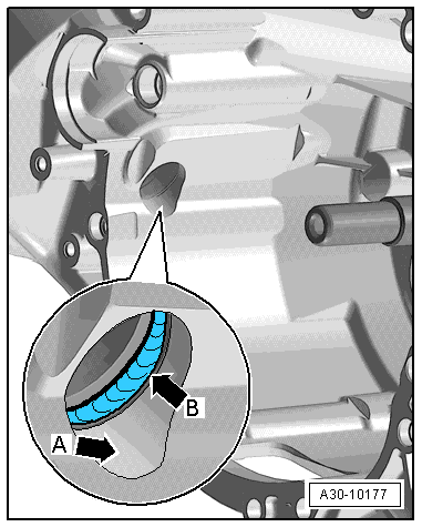
- Always clean the left flange shaft, the transmission housing in the area where the differential is accessed -arrow A- and the shaft seal -arrow B-.
 Note
Note
Replace the shaft seal between the differential and transmission housing -arrow B- if it is damaged. Refer to → Chapter "Left Seal, Replacing".
- Fill the space between the sealing- and dust lip half way with sealing grease. Refer to the Parts Catalog.
- Clean the left flange shaft thoroughly.
The Following Work Must be Performed on the Listed Vehicle Types Up to the Specified VIN:
.png)
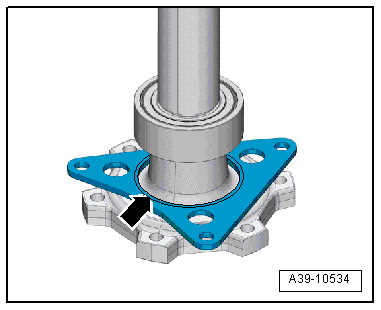
- Check the pre-tension on the ball bearing for the left flange shaft based on the wear pattern on the bearing bracket -arrow-. Refer to → Chapter "Left Flange Shaft Ball Bearing Pre-Tension, Checking and Adjusting".
- Optimize the pre-tension on the ball bearing for the left flange shaft if necessary. Refer to → Chapter "Pre-Tension on Ball Bearing, Optimizing, Left Flange Shaft".
- Adjust the pre-tension on the ball bearing for the left flange shaft if necessary. Refer to → Chapter "Pre-Tension on Ball Bearing, Adjusting, Left Flange Shaft".
For all Vehicle Models
- Install the flywheel. Refer to → Chapter "Flywheel, Removing and Installing".
- Rotate the flywheel. Refer to -1- until the opening to the differential -arrow 3- is seen.
- Install the left flange shaft -2- into the transmission -arrow B-. When doing this, insert the flange shaft centrally into the shaft seal on the front differential -arrow 3-.
 Note
Note
- If the flange shaft is not centered, the flange shaft splines -2- will damage the shaft seal between the final drive and the transmission housing.
- The shaft seal must be replaced if it is damaged.
- Ignore -arrow A-.
- Fill with transmission fluid (MTF). Refer to → S tronic Transmission; Rep. Gr.39; Transmission Fluid; Transmission Fluid, Draining and Filling.

Left Flange Shaft Ball Bearing Pre-Tension, Checking and Adjusting
Left Flange Shaft Ball Bearing Pre-Tension, Checking
Check the Ball Bearing Pre-Tension Using the Wear Pattern on the Bearing Bracket -arrow-.
 Note
Note
- The pre-tension on the left flange shaft ball bearing must be checked only on certain vehicles. Refer to the table for a list of the vehicles.
- This is not necessary on vehicles built later because they have been redesigned.
- The left flange shaft is removed. Refer to → Chapter "Left Flange Shaft, Removing and Installing".

Wear Pattern "A"
- Small indentations near the hole on the bearing bracket -arrows-.
- No trace of wear or material erosion.
- Optimize the pre-tension on the ball bearing for the left flange shaft. Refer to → Chapter "Pre-Tension on Ball Bearing, Optimizing, Left Flange Shaft".
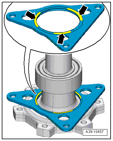
Wear Pattern "B"
- Traces of wear, if necessary, with material erosion all around the hole on the bearing bracket -arrow-.
- Adjust the pre-tension on the left flange shaft bearing. Refer to → Chapter "Pre-Tension on Ball Bearing, Adjusting, Left Flange Shaft".
- Replace the bearing bracket, the ball bearing and the circlip. Refer to → Chapter "Left Flange Shaft Ball Bearing Mounting Bracket, Removing and Installing".
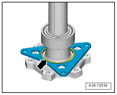
Pre-Tension on Ball Bearing, Optimizing, Left Flange Shaft
 Note
Note
- The pre-tension on the left flange shaft ball bearing must be optimized only on certain vehicles. Refer to the table for a list of the vehicles.
- This is not necessary on vehicles built later because they have been redesigned.
Procedure
- The left flange shaft is removed. Refer to → Chapter "Left Flange Shaft, Removing and Installing".
Conditions for optimizing:
- The bearing bracket does not show any traces of wear or material erosion.
- Small indentations near the hole on the bearing bracket -arrows- are permissible.

- Bearing bracket with wear pattern "A".
- A shim is inserted into the bearing seat on the transmission to optimize the pre-tension on the ball bearing.
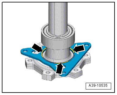
- Insert a Shim -0B4 409 227--1- into the bearing seat on the transmission before installing the flange shaft to improve the pre-tension.
- Install the left flange shaft. Refer to → Chapter "Left Flange Shaft, Removing and Installing".
Pre-Tension on Ball Bearing, Adjusting, Left Flange Shaft
 Note
Note
- The pre-tension on the left flange shaft ball bearing must be optimized only on certain vehicles. Refer to the table for a list of the vehicles.
- This is not necessary on vehicles built later because they have been redesigned.
- The left flange shaft is removed. Refer to → Chapter "Left Flange Shaft, Removing and Installing".
- Bearing bracket with wear pattern "B".
- The bearing bracket and ball bearing must be replaced. Refer to → Chapter "Left Flange Shaft Ball Bearing Mounting Bracket, Removing and Installing"

Procedure
- Clean off any dirt and corrosion from the contact surface -arrow- using 150 grain sand paper.
 Note
Note
It is not necessary to sand the contact surfaces all the way down to bare metal. It is enough to just remove any dirt and corrosion.
- Clean the contact surface and bearing seat.
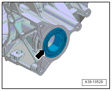
- Install the new left flange shaft ball bearing -arrow- into the bearing seat.
Next procedure:
- By bearing oversize (the bearing sticks out slightly above the contact surface).
- With bearing undersize (the bearing sits deeper than the contact surface).
Procedure If There Is Bearing Oversize
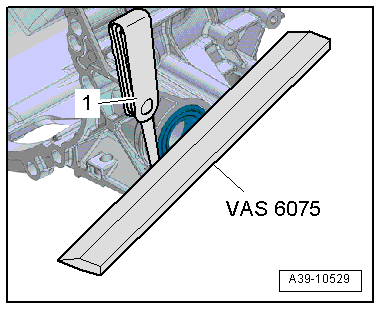
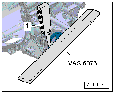
- Place Straight Edge - 500mm -VAS6075- straight across the bearing and determine the distance to the contact surface on the transmission housing on both sides with the feeler gauge.
- Write down the measured value.
- Place the straight edge 90º offset across the bearing and determine the distance to the contact surface on the transmission housing on both sides with the feeler gauge.
- Write down the measured value.
Selecting the Shim(s):
 Note
Note
Use the smallest value take from the four values to select the shim(s).
- Specified value, bearing oversize = 0.5 to 0.8 mm
.png)
Example:
1 shim:
0.1 mm + 0.3 mm = 0.4 mm, "bearing pre-load is too small"
2 shims:
0.1 mm + 0.3 mm + 0.3 mm = 0.7 mm, "bearing pre-load is in the specified range"
- Result: Insert two 0.3 mm shims to reach the bearing pre-load = 0.7 mm within the 0.5 to 0.8 mm specified value.
Procedure If There Is Bearing Undersize
 Note
Note
The bearing undersize can only be determined in the described procedure.
- Place Straight Edge - 500mm -VAS6075- straight across the contact surface on the transmission housing and measure the distance to the bearing on both sides with a feeler gauge.
- Write down the measured value.
- Place straight edge 90º offset across the contact surface on the transmission housing and measure the distance to the bearing on both sides with a feeler gauge.
- Write down the measured value.
Selecting the Shim(s):
 Note
Note
- Use the largest value take from the four values to select the shim(s).
- Enter the measured bearing undersize as negative value ("-") into the calculation.
- Specified value, bearing oversize = 0.5 to 0.8 mm
.png)
Example:
1 shim:
-0.15 mm + 0.3 mm = 0.15 mm, "bearing pre-load is too small"
3 Shims:
-0.15 mm + 0.3 mm + 0.3 mm + 0.3 mm = 0.75 mm, "bearing pre-load is in the specified range"
- Result: A 0.75 mm bearing pre-load within the specified value of 0.5 to 0.8 mm is reached by installing three 0.3 mm shims.
Continuation for All
- Replace the bearing bracket, the ball bearing and the circlip. Refer to → Chapter "Left Flange Shaft Ball Bearing Mounting Bracket, Removing and Installing".
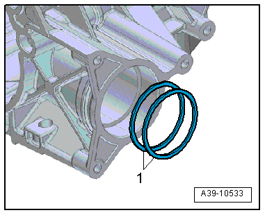
- Insert the determined number of shims -0B4 409 227- item -1- into the bearing seat on the transmission before installing the flange shaft.
- Install the left flange shaft. Refer to → Chapter "Left Flange Shaft, Removing and Installing".
Left Flange Shaft Ball Bearing Mounting Bracket, Removing and Installing
Special tools and workshop equipment required
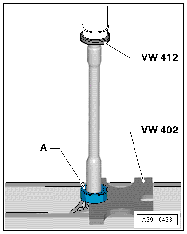
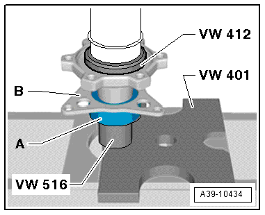
- Press Plate -VW401-
- Press Plate -VW402-
- Press Piece - Multiple Use -VW412-
- Press Piece - 42mm -VW516-
- Remove the left flange shaft. Refer to → Chapter "Left Flange Shaft, Removing and Installing".
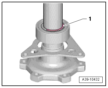
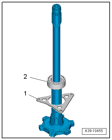
- Remove the locking ring -1- from the flange shaft.
- Remove the ball bearing -A- from the flange shaft
- Install the new bearing bracket -1-.
- Installed position: The printed side faces the drive axle flange.
- Install the new ball bearing -2-.
- Install the ball bearing -A- all the way on with the bearing bracket -B- installed.
- Install the circlip -1- in the flange shaft groove.

Right Flange Shaft, Removing and Installing
Special tools and workshop equipment required
- Bearing/Bushing Installer - Multiple Use -VW295A-
- Slide Hammer Set -VW771-
- Lifting Eyebolt -3368-
- Used Oil Collection and Extraction Unit -SMN372500-
- Grease. Refer to the Parts Catalog.
- M10 nut, quantity: 2
Removing
- Secure the transmission on the Engine And Transmission Holder -VAS6095-. Refer to → Chapter "Securing on Engine and Transmission Holder".
- Place the Used Oil Collection and Extraction Unit -SMN372500- under the transmission.
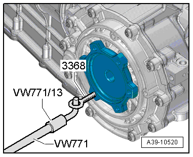
- Install the Lifting Eyebolt -3368- into a threaded hole in the right flange shaft.
- Position the Slide Hammer Set -VW771- with the -VW771/13- on the Lifting Eyebolt -3368- and remove the flange shaft.
Installing
Install in reverse order of removal. Note the following:
 Note
Note
Replace the circlip on the right flange shaft.
- Clamp the flange shaft in a vise with jaw protectors. Remove the old circlip from the groove in the flange shaft using the new circlip -A-.
- Fill the space between the sealing- and dust lip half way with sealing grease. Refer to the Parts Catalog.
- Drive in the right flange shaft using the Bearing/Bushing Installer - Multiple Use -VW295A-.
- Fill the transmission fluid (MTF). Refer to → S tronic Transmission; Rep. Gr.39; Transmission Fluid; Transmission Fluid, Draining and Filling.
