Audi A6 Typ 4G: DRC Checking
DRC System Pressure Checking
Special tools and workshop equipment required
- DRC Pressure Tester -VAS6209/2-
- Hand Vacuum Pump -VAS6213-
DRC Pressure Tester -VAS6209/2- Bleeding
Use only approved oil for the bleeding procedure. Refer to the Parts Catalog.
 Note
Note
- The DRC Pressure Tester -VAS6209/2- must always be bled the first time it is used.
- If the DRC Pressure Tester -VAS6209/2- still shows a residual pressure greater than 0.5 bar (7.2 psi) (for example, from a previous reading), bleeding must not be done.
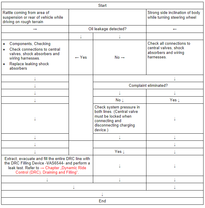
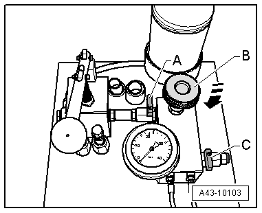
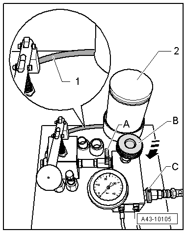
- To bleed pressure gauge -B- and line section -A-, install special tool as shown in illustration.
Note
The illustration shows bleeding process by extracting hydraulic fluid using a Hand Vacuum Pump -VAS6213-.
- Bleed process must be performed until air bubbles are no longer visible in hose -C-.
- Disconnect hose -C and D- and perform system pressure check.
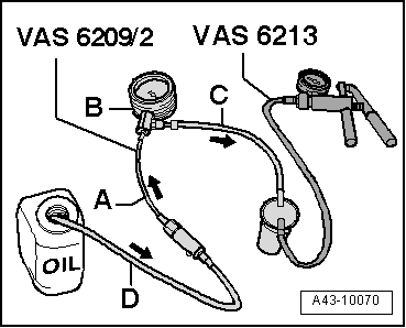
System pressure check is performed on front shock absorber of corresponding DRC line.
- Remove the cap from the extract/fill valve and connect the DRC Pressure Tester -VAS6209/2-.
- Read the system pressure on the DRC Pressure Tester -VAS6209/2-.
Note
The pressure on the DRC Pressure Tester -VAS6209/2-DRC Pressure Tester -VAS6209/2- increases slowly and takes approximately two minutes. DRC system pressure can only be read when DRC Pressure Tester -VAS6209/2- needle has finally come to a stop.
- Disconnect the DRC Pressure Tester -VAS6209/2- and install the dust cap.
Note
A small oil leak at the connection that results from connecting or disconnecting the DRC Pressure Tester -VAS6209/2- is not critical. Multiple measurements should be avoided since the system loses a little amount of oil each time the DRC Pressure Tester -VAS6209/2- is connected. Every connection results in a pressure decrease of approximately 0.3 bar (4.3 psi) from the previous reading. Multiple repeated measurements decrease system pressure below minimum pressure or failure.
- If the pressure is not OK, determine the cause and service the system.
DRC System Pressure Values
Pressure value. Refer to reference temperature of 20 ºC (68 ºF)
- 16 bar (232 psi) = operating pressure
- 15 bar - 16 bar (218 - 232 psi) = central valve new or as good as new
- 14 bar -15 bar (203 - (218 psi) = normal range of operation, system OK
- < 14 bar (203 psi) = system leaking or not filled completely, air entering system, central valve has no pressure/is empty.
Dynamic Ride Control (DRC), Draining and Filling
Note
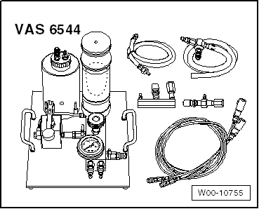
Extracting, evacuating and filling the whole DRC line (lines/shock absorber and central valve) is performed with the DRC Filling Device -VAS6544- Depending on the DRC system equipment in the dealership, the equipment may need to modified or updated to match DRC Filling Device -VAS6544-. The following choices are possible:
Special tools and workshop equipment required
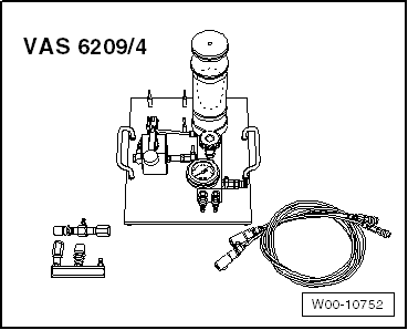
- DRC Filling Device -VAS6209/4-
- The DRC Filling Device -VAS6209/4- serves as an upgrade to the DRC Charging Device -VAS6209- already found in dealerships.
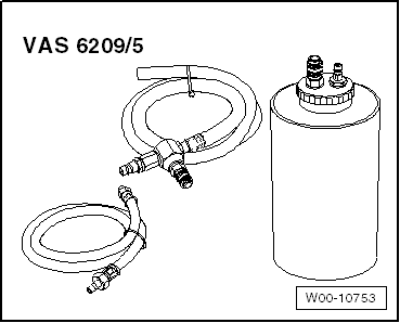
- Retrofit Kit, DRC System -VAS6209/5-
- The Retrofit Kit, Retrofit Kit, DRC System -VAS6209/5- is needed if the dealership has the DRC Charging Device, Pressure Pump -VAS6209/3- and wants to upgrade the Filling Device for DRC System -VAS6544-. The DRC System Supplementary Kit -VAS6209/6- is also necessary.
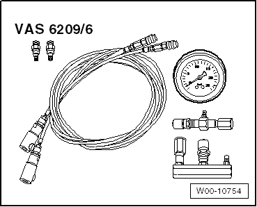
- DRC System Supplementary Kit -VAS6209/6-
- The Supplement Kit, DRC System -VAS6209/6- is needed to upgrade the DRC Charging Device, Pressure Pump -VAS6209/3- to the Filling Device for DRC System -VAS6544-. The requirement is that the dealership already has the DRC Charging Device -VAS6209-. If the dealership does have the DRC Charging Device -VAS6209-, then the Retrofit Kit, DRC System -VAS6209/5- must also be obtained.
- DRC Filling Device -VAS6544-
Note
Updating the equipment for the DRC system must be done one time only. It is not necessary to convert back again. The procedure for draining and filling the complete DRC system is described using the DRC Filling Device -VAS6544-.
Only approved oil for filling and draining must be used. Refer to the Parts Catalog.
As a replacement part, shock absorbers and lines are delivered empty.
Filling must only be performed at ambient temperature of approximately 20 ºC (68 ºF).
Lines/shock absorbers and central valves may only be suctioned, evacuated and filled when they are installed and connected.
 Caution
- Extracting, evacuating and filling the DRC line on vehicles with the variable damping may be performed only when the damping setting is set to "COMFORT".
- To extract, evacuate and fill the DRC line, start the Fill DRC"function" on the Vehicle Diagnostic Tester under address word 14 in "Guided Functions".
- If the mode is activated, the system goes into "COMFORT" mode and can no longer be changed manually. The yellow indicator lamp in the instrument cluster turns on when filling mode is active.
While filling the DRC system, the gas reservoir to the pressure clamps is automatically checked for leaks at the piston in the central valve.
 WARNING
Always wear safety goggles!
Valves of filling device are open when ratchet levers are parallel to direction of flow.
Note
The valves must be kept closed during transport and storing the DRC Filling Device -VAS6544-.
Lines must not be bent.
Required Equipment
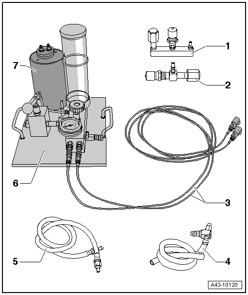
1 - Not Required
2 - Not Required
3 - Fill lines with Quick-Release Fastener
4 - Venturi Injector with Exhaust Hose
- From the DRC Charging Device -VAS6209-
5 - Connecting Hose
- From the DRC Charging Device -VAS6209-
6 - DRC Filling Device -VAS6544-
7 - Container for Used Oil
- Empty before starting the work
- Identification: red dot
Note
- Before filling the DRC system, make sure the oil reservoir for the DRC Charging Device -VAS6544- and the line between the pressure pump and oil reservoir are filled with oil.
- The used oil container on the DRC Filling Device -VAS6544- must be empty and must be emptied after each charge.
Drain Old Oil Reservoir
- Remove the cap -arrow- from the old oil reservoir -1- and drain the old oil.
- Install the cap -arrow- on the old oil reservoir -1-.
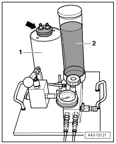
DRC Filling Device -VAS6544- Filling and Bleeding
- Fill the oil reservoir -2- with new oil up to the marking and position the O-ring to the height of the oil level. Refer to the Parts Catalog.
- Close the shut-off valve -A and C- on the DRC Filling Device -VAS6544-.
- Close the needle valve -B-.
- Connect the hose -2- to the old oil reservoir -arrow- and to the quick-release fastener -4- on the DRC Filling Device -VAS6544-.
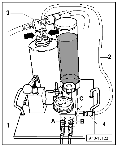
- Connect the Venturi injector -3- and vent hose to the old oil reservoir -arrow- as illustrated.
- Connect the compressed air to the Venturi injector -3-.
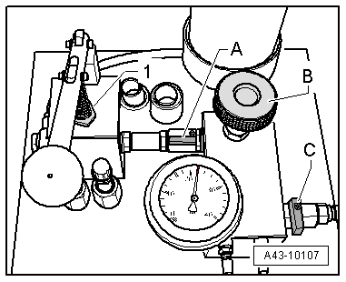
- Open the locking valve -C-.
- Open the locking valve -A- briefly, for approximately one to two seconds, until the connecting line -1- between the oil reservoir -2- and pressure pump is filled and does not contain bubbles.
- Close the locking valve -C-. Remove the compressed air connector form the Venturi injector.
Extracting/Evacuating
Caution
- Extracting, evacuating and filling the DRC line on vehicles with the variable damping may be performed only when the damping setting is set to "COMFORT".
- To extract, evacuate and fill the DRC line, start the Fill DRC"function" on the Vehicle Diagnostic Tester under address word 14 in "Guided Functions".
- If the mode is activated, the system goes into "COMFORT" mode and can no longer be changed manually. The yellow indicator lamp in the instrument cluster turns on when filling mode is active.
WARNING
Always wear safety goggles!
- In vehicles with variable damping, start the Fill DRC"function" on the Vehicle Diagnostic Tester under address word 14 in "Guided Functions".
- Turn the front wheel on the side to be suctioned toward the outside.
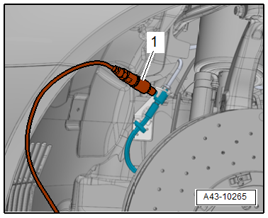
- Remove the dust cap from the front suction/fill valve.
- Connect the fill line and quick-release fastener -1- from the Charging Device For DRC System -VAS6544--Item 3- to the front suction/fill valve on the line to be suctioned.
- Remove the rear wheel on the side of the line to be suctioned.
- Free up the wheel housing liner for the rear suction/fill valve.
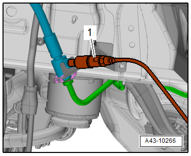
- Remove the dust cap from the rear suction/fill valve.
- Connect the fill line and quick-release fastener -1- from the Charging Device For DRC System -VAS6544--Item 3- to the rear suction/fill valve on the line to be suctioned.
- Connect the fill lines -Item 3- to the connections -A and B- on the DRC Filling Device -VAS6544-.
The shut-off valve -A and C- on the DRC Filling Device -VAS6544- closed.
Needle valve -B- closed.
The hose -2- is connected to the used oil container -arrow- and to the DRC Filling Device -VAS6544--4-.
Venturi injector -3- connected to the old oil reservoir vent hose -arrow- on the DRC Filling Device -VAS6544-.
Compressed air to the Venturi injector -3- connected.
- Open the valve -C- until the last of the oil is extracted from the DRC system. (Visible on the return hose -2- to the used oil reservoir).
- When the pressure manometer shows approximately negative 0.9 bar (13 psi), close the valve -C- and disconnect the compressed air hose from the Venturi injectors.
- Check for leaks.
Note
Vacuum must be stable for at least two minutes at negative 0.9 bar (13 psi).
- Check the oil level on the oil reservoir, fill with new oil up to the marking if necessary and position the O-ring to the height of the oil level. Refer to the Parts Catalog.
Caution
Extracting, evacuating and filling the DRC on vehicles with the 3-stage damping may be performed only when the damping setting is set to "COMFORT".
Filling
Caution
- Extracting, evacuating and filling the DRC line on vehicles with the variable damping may be performed only when the damping setting is set to "COMFORT".
- To extract, evacuate and fill the DRC line, start the Fill DRC"function" on the Vehicle Diagnostic Tester under address word 14 in "Guided Functions".
- If the mode is activated, the system goes into "COMFORT" mode and can no longer be changed manually. The yellow indicator lamp in the instrument cluster turns on when filling mode is active.
- Open the needle valve -B- approximately two turns and let the oil run out of the oil reservoir on the DRC Filling Device -VAS6544- into the evacuated DRC system.
Oil flows from the reservoir into the connected DRC system. This is shown by the decreasing oil level in the oil reservoir. Depending on the amount of oil remaining after extraction, the procedure may take several minutes. As the system fills up, the oil level goes down slower. If the level of the oil no longer moves, the first step of the filling process is complete.
- Close the needle valve -B-.
- Open the valve -A- and fill the DRC system to 22 bar (319 psi) by pumping the lever on the hand pump -1- several times.
Note
While filling, make sure the oil reservoir on the DRC Filling Device -VAS6544- does not run dry; fill with reservoir with new oil if necessary.
- When a pressure of 22 bar (319 psi) is reached, close the valve -A- and do not pump the hand pump lever any more.
Note
- Exceeding the maximum pressure of 22 bar (319 psi) does not improve the filling process. Caution!: There is a risk of damaging DRC system components as well as the DRC Filling Device -VAS6544-.
- If the pressure does not reach 22 bar (319 psi) or if it continually drops, check all connections for damage or leaks. If no issues are found on the outside, the gas reservoir to the pressure clamps on the piston on the inside of the central valve is leaking. Replace the central valve.
- Open the needle valve -B- slightly and let the pressure drop to 16 bar (232 psi).
- Close the valve -B- when the indicator on the pressure manometer reaches the 16 bar (232 psi) marking.
Note
The 16 bar (232 psi) graduation line on the scale is colored in green depending and the version and model of the pressure gauge. The marking has no meaning for this procedure.
DRC system is filled.
- Disconnect the fill line and quick-release fastener on the DRC Filling Device -VAS6544--Item 3- from the rear and front suction/fill valve.
- Mount the rear wheel.
- Install the dust cap on the rear and front suction/fill valve.
- End the Fill DRC"function" on the Vehicle Diagnostic Tester on vehicles with variable damping.
Special Tools
Special tools and workshop equipment required
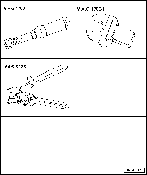
- Torque Wrench 1783 - 2-10Nm -VAG1783-
- Torque Wrench 1783 - Open Jaw - 10mm -VAG1783/1-
- Hose Cutting Pliers -VAS6228-
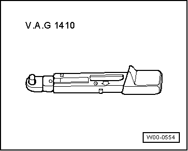
- Torque Wrench 1410 -VAG1410-
- DRC Pressure Tester -VAS6209/2-
- Hand Vacuum Pump -VAS6213-
- DRC Filling Device -VAS6209/4-
- Retrofit Kit, DRC System -VAS6209/5-
- DRC System Supplementary Kit -VAS6209/6-
- DRC Filling Device -VAS6544-