Audi A6 Typ 4G: DVD/CD Changer
Connector Assignments
CD Changer -R41- Connector Assignment
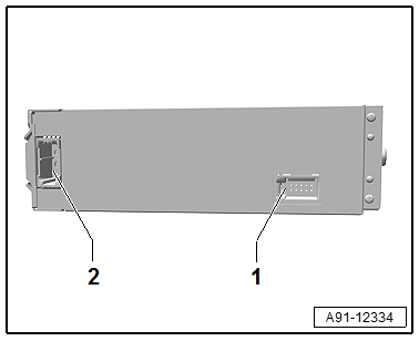
CD Changer -R41-
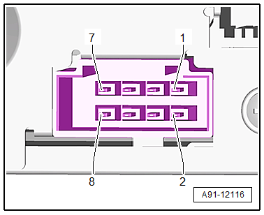
1 - 8-Pin Connector -T8g-
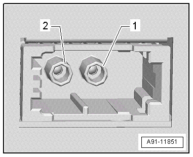
2 - MOST Bus
 Note
Note
Unlisted connector terminals are not assigned.
1 - 8-Pin Connector -T8g-
1 - Terminal 31
2 - Terminal 30
3 - Not Assigned
4 - Not Assigned
5 - Ring-break Diagnostic Cable
2 - MOST Bus
1 - Output
2 - Input
DVD Changer -R161- Connector Assignment, through MY 2014
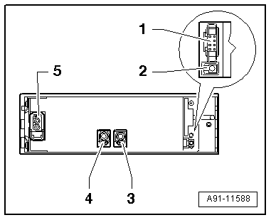
DVD Changer -R161-
1 - 8-Pin Connector -T8g-
2 - TV Tuner -R78- CVBS input (Not available for North America)
3 - CVBS output to the Information Electronics Control Module 1 -J794-
4 - Not Assigned
5 - MOST Bus
Note
Unlisted connector terminals are not assigned.
1 - 8-Pin Connector -T8g-
1 - Terminal 31
2 - Terminal 30
3 - Not Assigned
4 - Not Assigned
5 - Ring-break Diagnostic Cable
5 - MOST Bus
1 - Input
2 - Output
DVD Changer -R161- Connector Assignment, from MY 2015
DVD Changer -R161-
1 - 8-Pin Connector -T8g-
2 - MOST Bus
Note
Unlisted connector terminals are not assigned.
1 - 8-Pin Connector -T8g-
1 - Terminal 31
2 - Terminal 30
3 - Not Assigned
4 - Not Assigned
5 - Ring-break Diagnostic Cable
5 - MOST Bus
1 - Input
2 - Output
CD Changer, Removing and Installing
Special tools and workshop equipment required
- Radio Removal Tool -T10057-
- Fiber-Optic Repair Set - Connector Protective Caps -VAS6223/9-.
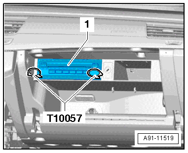
The CD Changer -R41- is located inside the glove compartment.
Note
If replacing the control module, select the "Replace Control Module" function on the Vehicle Diagnostic Tester.
Removing
- Open the glove compartment.
- Remove any CDs still in the CD Changer -R41-.
- Turn off the ignition and all electrical consumers and remove the ignition key.
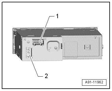
- Insert the two clips on the Radio Removal Tool -T10057- in the release slits on the CD Changer -R41--1- until they engage. Points on the grip eyelets of tool face outward.
- Remove the CD Changer -R41- from the frame.
- Disconnect all of the connectors from the CD Changer -R41-.
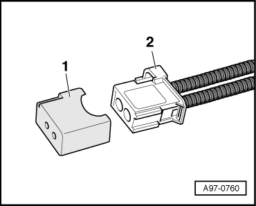
- Insert the Fiber-Optic Repair Set - Connector Protective Caps -VAS6223/9--1- onto the MOST Bus connector -2-.
- Press the locking latches on the CD Changer -R41- to remove the Radio Removal Tool -T10057-.
Installing
- Connect all the connectors.
- Push the CD Changer -R41- into the mounting frame until it engages.
DVD Changer, Removing and Installing
Special tools and workshop equipment required
- Radio Removal Tool -T10057-
- Fiber-Optic Repair Set - Connector Protective Caps -VAS6223/9-.
The DVD Changer -R161- is located inside the glove compartment.
Note
If replacing the control module, select the "Replace Control Module" function on the Vehicle Diagnostic Tester.
Removing
- Open the glove compartment.
- Remove any DVD still in the DVD Changer -R161-.
- Turn off the ignition and all electrical consumers and remove the ignition key.
- Insert the two clips on the Radio Removal Tool -T10057- in the release slits on the DVD Changer -R161--1- until they engage. Points on the grip eyelets of tool face outward.
- Remove the DVD Changer -R161- from the mounting frame.
- Unlock and disconnect the connectors from the DVD Changer -R161-.
- Insert the Fiber-Optic Repair Set - Connector Protective Caps -VAS6223/9--1- onto the MOST Bus connector -2-.
- Press the locking latches on the DVD Changer -R161- to remove the Radio Removal Tool -T10057-.
Installing
- Connect all the connectors.
- Push the DVD Changer -R161- into the mounting frame until it engages.
