Audi A6 Typ 4G: Upper Transverse Link, Removing and Installing
 Note
Note
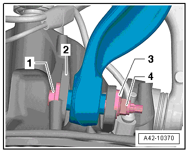
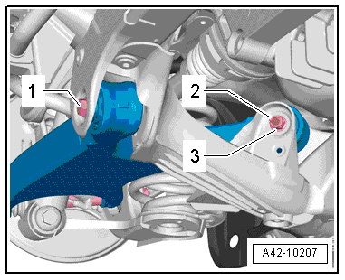
Due to the inaccessibility of the inner threaded connection -1-, the upper control arm can only be removed when the subframe has been removed.
Special tools and workshop equipment required
- Torque Wrench 1332 40-200Nm -VAG1332-
Removing
- Remove subframe. For FWD vehicles. Refer to → Chapter "Subframe, Removing and Installing, FWD Vehicles"; for AWD vehicles. Refer to → Chapter "Subframe, Removing and Installing, AWD Vehicles".
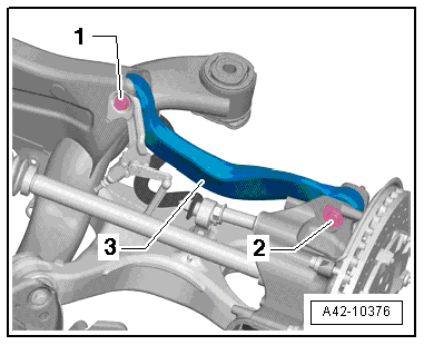
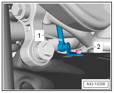
- Mark the installed position of the adjusting bolt -2- to the wheel bearing housing.
- Separate connections -1 and 2-.
- Remove upper transverse link -3-.
Installing
Note
Replace the bolts and the self-locking nuts.
Installation position of the transverse link to the subframe
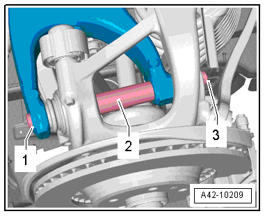
- Install the upper control arm -3- on the threaded connection -1- by hand.
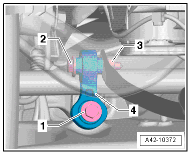
- Place a piece of flat iron -1- flat on the highest point of the subframe -arrow-.
- Position the upper control arm -2- so dimension a = 11 mm between the flat iron -1- and the stamping burr on the upper control arm -2-.
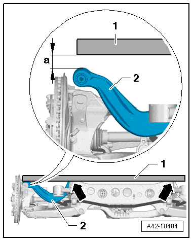
- Tighten the upper control arm -3- on the subframe in this position.
- Screw wheel bearing housing on control arm and tighten new nut to 20 Nm. Note the installation position of the centering washer -2-.
- Install the subframe. For FWD vehicles. Refer to → Chapter "Subframe, Removing and Installing, FWD Vehicles"; for AWD vehicles. Refer to → Chapter "Subframe, Removing and Installing, AWD Vehicles".
- Loosen the nut -4-.
- Lift the wheel bearing into the curb weight position (refer to → Chapter "Wheel Bearing in Curb Weight, Lifting Vehicles with Coil Spring") or control position (refer to → Chapter "Wheel Bearing in Control Position, Lifting Vehicles with Air Suspension") and tighten the nut -4-.
- Install rear wheel. Refer to → Chapter "Wheels and Tires".
- To determine if an axle alignment is required, see Table. Refer to → Chapter "Evaluating Need for Axle Alignment".
The axle alignment must be performed on a VW/Audi approved alignment stand.
Lower Transverse Link, Removing and Installing
Special tools and workshop equipment required
- Torque Wrench 1331 5-50Nm -VAG1331-
- Torque Wrench 1332 40-200Nm -VAG1332-
- Engine and Gearbox Jack -VAS6931-
- Tensioning Strap -T10038-
- Engine/Gearbox Jack Adapter - Wheel Hub Support -T10149-
Removing
- Remove the rear wheel. Refer to → Chapter "Wheels and Tires".
Vehicles with Steel Suspension
- Remove the coil spring. Refer to → Chapter "Spring, Removing and Installing, Coil Spring".
Vehicles with Air Suspension
- Bleed the rear axle air spring. Refer to → Chapter "System, Venting or Filling".
Continuation for All Vehicles
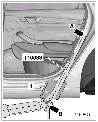
- Secure the vehicle to the hoist lifting arms -arrow B- with the Tensioning Strap -T10038- over the striker pin -arrow A-.
- Place a piece of foam rubber -1- between the sill panel and the Tensioning Strap -T10038- and then tension the Tensioning Strap -T10038-.
Note
Be careful not to scratch the sill panel.
 Caution
The vehicle could fall off the hoist if it is not secured.
- Remove the diagonal brace. Refer to → Chapter "Diagonal Braces, Removing and Installing".
- The rear section of the exhaust system must be removed first, as in the previous step, to remove the left lower transverse link. Refer to → Rep. Gr.26; Exhaust Pipes/Mufflers; Overview - Muffler.
- Remove the bolt -2- from the vehicle level sensor -1-.
- Remove the bolt -1-.
Note
Ignore Items -2, 3 and 4-.
- Remove the nut -3-.
- Remove the bolt -1- and the spacer -2-.
- Remove the bolt -1-.
- Remove the nut -3- and bolt -2-.
- Remove the lower transverse link. While doing this, have another technical push the wheel bearing housing upward and away.
Note
Be careful not to damage the wire and brake hose when pushing the wheel bearing housing. The joints in the drive axle must not touch each other by bending on a vehicle with AWD.
Installing
Install in reverse order of removal. Note the following:
Note
- Bonded rubber bushings have a limited range of motion. Only tighten suspension bolts when vehicle is in curb weight or control position.
- Wheel bearing, lifting to curb weight position on vehicles with coil springs. Refer to → Chapter "Wheel Bearing in Curb Weight, Lifting Vehicles with Coil Spring".
- For vehicles with air spring suspension, lift wheel suspension in control position. Refer to → Chapter "Wheel Bearing in Control Position, Lifting Vehicles with Air Suspension".
- Insert the lower control arm and install the bolt -1- loosely.
- Install the bolt -2- and install the nut -3- loosely.
- Insert the bolt -1- with the spacer tube -2- and install the nut -3- loosely.
Caution
Do not tighten the threaded connection using the nut -3-.
- Tighten the bolt -1-.
- Tighten the rest of the threaded connections.
- Install the coil spring. Refer to → Chapter "Spring, Removing and Installing, Coil Spring".
- Install rear wheel. Refer to → Chapter "Wheels and Tires".
- Fill the rear axle air springs. Refer to → Chapter "System, Venting or Filling".
- To determine if an axle alignment is required, see Table. Refer to → Chapter "Evaluating Need for Axle Alignment".
The axle alignment must be performed on a VW/Audi approved alignment stand.
- On vehicles with automatic head lamp range control, perform headlamp basic setting. Refer to → Electrical Equipment; Rep. Gr.94; Headlamp; Headlamp, Adjusting.
- If the level control sensor is removed or installed on a vehicle with electronic damping or if the linkage was loosened, the control position must be programmed again by starting the correct program on the Vehicle Diagnostic Tester in Guided Functions.
- If the control position was reprogrammed on vehicles with lane assist, the Directional Stabilization Assistance Control Module -J759- must be calibrated again. Refer to → Chapter "Driver Assistance Systems Front Camera, Calibrating".
Tie Rod, Removing and Installing
Special tools and workshop equipment required
- Torque Wrench 1332 40-200Nm -VAG1332-
- Track Rod Tool Insert -T40183-
Removing
Note
A vehicle with air suspension is described in the work procedure.
- Remove the rear wheel. Refer to → Chapter "Wheels and Tires".
- Loosen the wheel housing liner in the front area. Refer to → Body Exterior; Rep. Gr.66; Wheel Housing Liner; Rear Wheel Housing Liner, Removing and Installing and push to the side.
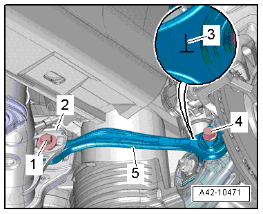
- Remove the bolt -4- first.
- Mark installation position of the eccentric bolt -1- to the subframe -2-.
- Remove the nut, the eccentric washer and the eccentric bolt -1-.
- Remove the tie rod -5-.
Note
Ignore Item -3-.
Installing
Install in reverse order of removal. Note the following:
Note
- Bonded rubber bushings have a limited range of motion. Only tighten suspension bolts when vehicle is in curb weight or control position.
- For lifting the wheel bearing into curb weight position, vehicles with steel suspension. Refer to → Chapter "Wheel Bearing in Curb Weight, Lifting Vehicles with Coil Spring".
- For vehicles with air spring suspension, lift wheel suspension in control position. Refer to → Chapter "Wheel Bearing in Control Position, Lifting Vehicles with Air Suspension".
- Insert the tie rod -5-.
- Pay attention to the mark -3-. Refer to → Fig. "Tie Rod on A Vehicle with Steel Suspension" or → Fig. "Tie Rod on A Vehicle with Air Suspension".
- Insert the eccentric bolt -1- completely first and line it up with the marking when removing.
- Insert and tighten the bolt -4-.
- Tighten the eccentric washer and the new nut for the eccentric bolt -1- hand-tight. Tighten the nut to the tightening specification only after the axle alignment.
- Install rear wheel. Refer to → Chapter "Wheels and Tires".
- To determine if an axle alignment is required, see Table. Refer to → Chapter "Evaluating Need for Axle Alignment".
The axle alignment must be performed on a VW/Audi approved alignment stand.
