Audi A6 Typ 4G: Electrical/Electronic Components and Component Locations
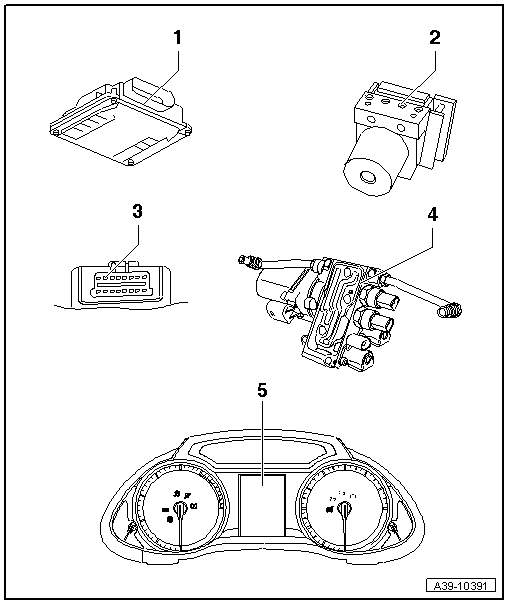
1 - All Wheel Drive Control Module -J492-
- Installed location A4 Sedan, A5 Coupe and A5 Cabriolet. Refer to → Fig. " All Wheel Drive Control Module -J492- in the A4 Sedan, A5 Coupe and the A5 Cabriolet"
- Installed location A4 Avant. Refer to → Fig. " All Wheel Drive Control Module -J492- in the A4 Avant"
- Installed location A5 Sportback. Refer to → Fig. " All Wheel Drive Control Module -J492- in the A5 Sportback"
- Installed location A6 and A7. Refer to → Fig. " All Wheel Drive Control Module -J492- in the Audi A6/A7"
- Installed location A8. Refer to → Fig. " All Wheel Drive Control Module -J492- in the A8"
- Removing and installing. Refer to → Chapter "All Wheel Drive Control Module -J492-, Removing and Installing".
- Additional work after replacing the control module. Refer to → Chapter "All Wheel Drive Control Module -J492-, Additional Work after Replacing".
- Important signals from engine control module and ABS Control Module -J104- are transmitted via the Data bus to the All Wheel Drive Control Module -J492-.
2 - ABS Control Module -J104-
- Installation location, removing and installing.
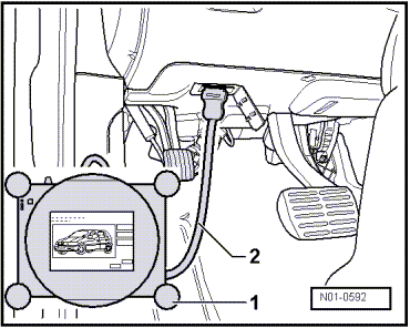
3 - Diagnostic Connection
- Installed location: Driver side footwell. Refer to → Fig. "Data Link Connector"
- Connect the Vehicle Diagnostic Tester and select the function. Refer to → Chapter "All Wheel Drive Control Module -J492-, Removing and Installing".
4 - Hydraulic Control Unit
- Component location: on rear final drive
- Removing and installing. Refer to → Chapter "Hydraulic Control Unit, Removing and Installing".
- Disassembling and assembling. Refer to → Chapter "Hydraulic Control Unit, Disassembling and Assembling".
- Hydraulic control unit with:
- All Wheel Drive Pump -V415-
- Oil Pressure/Temperature Sensor 2 -G640-
- Oil Pressure/Temperature Sensor -G437-
- All Wheel Drive Clutch Valve 2 -N446-
- All Wheel Drive Clutch Valve -N445-
5 - Display in Instrument Cluster
Data Link Connector
Component location: The data link connector for the Vehicle Diagnostic Tester is located in the driver side footwell.
All Wheel Drive Control Module -J492- in the A4 Sedan, A5 Coupe and the A5 Cabriolet
Component location: The All Wheel Drive Control Module -J492--A- is located in the spare wheel well in front of the battery.
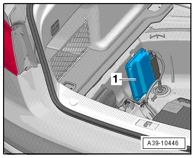
All Wheel Drive Control Module -J492- in the A4 Avant
Component location: The All Wheel Drive Control Module -J492--1- is in the luggage compartment on the right in front of the spare wheel well.
All Wheel Drive Control Module -J492- in the A5 Sportback
Component location: the All Wheel Drive Control Module -J492--1- is located on the right wheel housing behind the luggage compartment side trim panel.
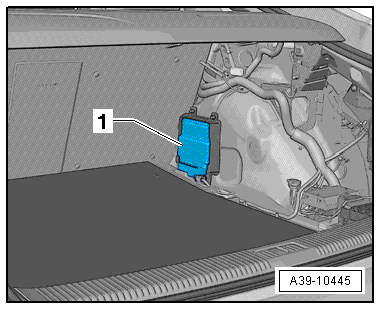
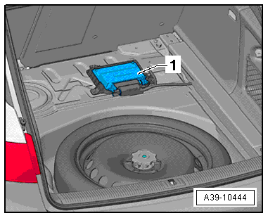
All Wheel Drive Control Module -J492- in the Audi A6/A7
Component location: The All Wheel Drive Control Module -J492--A- is located on the right in the spare wheel well.
All Wheel Drive Control Module -J492- in the A8
Component location: The All Wheel Drive Control Module -J492--A- is located on the left in the spare wheel well.
All Wheel Drive Control Module -J492-, Removing and Installing
 Note
Note
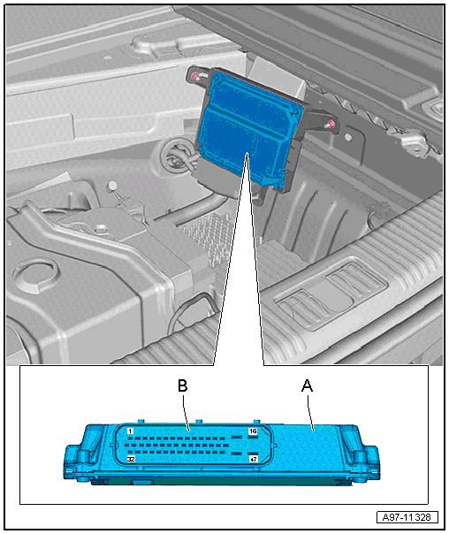
- All Wheel Drive Control Module -J492- component location -item 1-.
- Removing and installing is on the A4 Sedan.
- The ignition is off.
- Remove the luggage compartment floor covering.
- Remove the covering and the vehicle tools mount.
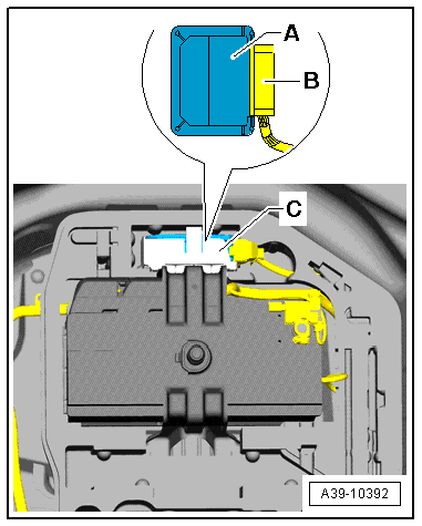
- Remove the All Wheel Drive Control Module -J492--A- from the bracket -C-.
- Disconnect the connector -B- from the All Wheel Drive Control Module -J492-.
- Install the All Wheel Drive Control Module -J492- in reverse order of removal.
- If the All Wheel Drive Control Module -J492- was replaced then additional work is necessary. Refer to → Chapter "All Wheel Drive Control Module -J492-, Additional Work after Replacing".
All Wheel Drive Control Module -J492-, Additional Work after Replacing
Note
Only perform the additional work only if the All Wheel Drive Control Module -J492- was replaced.
- Connect the Vehicle Diagnostic Tester and switch on the ignition.
- On the Vehicle Diagnostic Tester select the function 22 - Control Module, Replacing under Guided Functions in the directory 22 - AWD electronics.
- Follow the instructions given by the Vehicle Diagnostic Tester exactly.
"Adapt" the installed rear final drive to the All Wheel Drive Control Module -J492- with the Vehicle Diagnostic Tester.
Note
A system check will take place when the 22 - Control Module, Replacing function is complete. If malfunctions appear, then use "Guided Fault Finding" to correct them.
Overview - Rear Final Drive
 Caution
Only some components on the rear final drive can be disassembled.
- Currently both chambers -item 11- and -item 25- cannot be removed from the final drive.
- It is therefore currently not possible to repair the interior components.
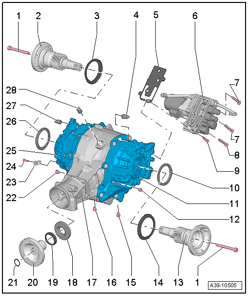
1 - Bolt
- 50 Nm + 180º turn
- Always replace.
2 - Right Flange Shaft
- Removing and installing. Refer to → Chapter "Flange Shaft Seals, Replacing, Rear Final Drive Removed".
- Do not confuse with the left flange shaft, they are different
3 - Protective Ring
- Replacing. Refer to → Chapter "Flange Shaft Protective Ring, Replacing".
4 - ATF Breather Pipe
- For the left chamber
- Clip onto the bleed pipe
5 - Gasket
- With strainer
6 - Hydraulic Control Unit
- With the All Wheel Drive Pump -V415- and lines to the chambers
- Removing and installing. Refer to → Chapter "Hydraulic Control Unit, Removing and Installing".
- Disassembling and assembling. Refer to → Chapter "Hydraulic Control Unit, Disassembling and Assembling".
7 - Bolt
- 20 Nm
- Quantity: 2
- M8; 50 mm long
- Follow the tightening sequence.
8 - Bolt
- 20 Nm
- M8; 50 mm long
- With a permanent seal under the bolt head
- Coat the threads with Sealing Compound -D 176 501 A1-.
- Follow the tightening sequence.
9 - Bolt
- 20 Nm
- M8; 30 mm long
- Follow the tightening sequence.
10 - Shaft Seal
- For the left flange shaft
- Replacing. Refer to → Chapter "Flange Shaft Seals, Replacing, Rear Final Drive Removed".
11 - Left Chamber
12 - ATF Check Plug
- 15 Nm
- Always replace.
- With permanent seal
13 - Left Flange Shaft
- Removing and installing. Refer to → Chapter "Flange Shaft Seals, Replacing, Rear Final Drive Removed".
- Do not confuse with the right flange shaft, they are different
14 - Protective Ring
- Replacing. Refer to → Chapter "Flange Shaft Protective Ring, Replacing".
15 - ATF Drain Plug
- 15 Nm
- Always replace.
- With permanent seal
16 - Gear Oil Drain Plug
- 15 Nm
- Always replace.
- With permanent seal
17 - Final Drive Housing
18 - Shaft Seal
- For the flange/driveshaft
- Replacing on rear final drive 0BF. Refer to → Chapter "Shaft Seal for Flange/Propshaft, Replacing".
- Replacing on rear final drive 0BE. Refer to → Chapter "Rear Final Drive 0BE - Replacing, Flange/Driveshaft Shaft Seal".
19 - Protective Ring
- Replacing. Refer to → Chapter "Flange/Driveshaft Seal, Replacing".
20 - Flange/Driveshaft
- Removing and installing on final drive 0BF. Refer to → Chapter "Shaft Seal for Flange/Propshaft, Replacing".
- Removing and installing on final drive 0BE. Refer to → Chapter "Rear Final Drive 0BE - Replacing, Flange/Driveshaft Shaft Seal".
21 - Circlip
- Always replace.
- Installing.
22 - Gear Oil Check Plug
- 15 Nm
- Always replace.
- With permanent seal
23 - Bracket
- For the wiring harness
24 - Bolt
- 9 Nm
25 - Right Chamber
26 - Shaft Seal
- For the right flange shaft
- Replacing. Refer to → Chapter "Flange Shaft Seals, Replacing, Rear Final Drive Removed".
27 - ATF Breather Pipe
- For the right chamber
- Clip onto the bleed pipe
28 - Final Drive Bleeder
- Clip onto the bleed pipe
