Audi A6 Typ 4G: Flange Shaft Protective Ring, Replacing
Flange Shaft Ring, Replacing, 0BC
- The ring can only be replaced with the final drive and the flange shaft removed.
Special tools and workshop equipment required
- Press Plate -VW401-
- Press Plate -VW402-
- Press Piece - Multiple Use -VW412-
- Press Piece - Lower Ball Joint - 3146-
- -3-Separating Tool - 22-115mm, for example Puller - Kukko Quick Action Separating Tool - 22-115mm -Kukko 17/2-
- The rear final drive is removed. Refer to → Chapter "Final Drive, Removing and Installing".
- Flange shaft removed. Refer to → Chapter "Left Seal, Replacing, 0BC".
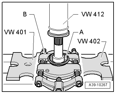
Removing the protective ring -A- from the flange shaft
B - Puller - Quick Action Separating Tool - 22-115mm, for example -Kukko 17/2-
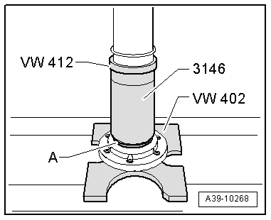
Installing the ring -A- on the flange shaft
- Ring installed position -A-: the larger outer diameter faces the flange.
Flange Shaft Ring, Replacing, 0BE, 0BF
- The ring can only be replaced with the final drive and the flange shaft removed.
Special tools and workshop equipment required
- Press Plate -VW401-
- Press Plate -VW402-
- Press Piece - Multiple Use -VW412-
- Bearing Installer - Differential Bearing -40 - 21-
- Seal Installer - Flywheel Oil Seal Kit - Press Sleeve -2003/1- from the Seal Installer - Flywheel Oil Seal Kit -2003-
- Bearing Installer - Wheel Bearing -3345-
- Separating Tool - 22-115mm, such as Puller - Kukko Quick Action Separating Tool - 22-115mm -17/2-
- The rear final drive is removed. Refer to → Chapter "Final Drive, Removing and Installing".
- Flange shaft removed. Refer to → Chapter "Left Seal, Replacing, 0BE, 0BF".
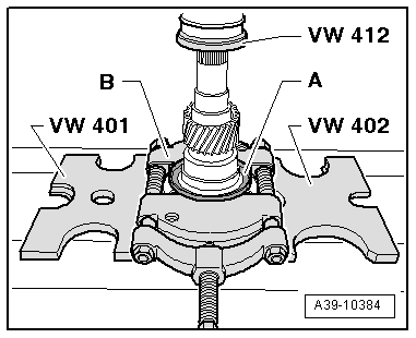
Removing the protective ring -A- from the flange shaft
B - Separating Tool - 22-115mm, such as Puller - Kukko Quick Action Separating Tool - 22-115mm -Kukko 17/2-
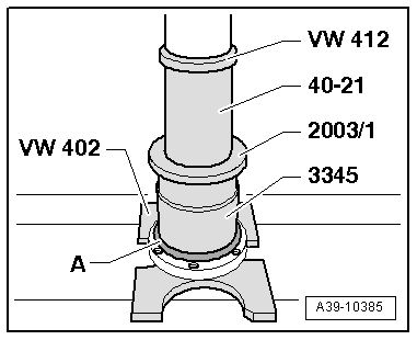
Carefully press the ring -A- onto the flange shaft.
- Protective ring installation location -A-: The larger outer diameter on the protective ring faces the Bearing Installer - Wheel Bearing -3345-.
Flange Input Shaft Ring, Replacing
Flange Input Shaft Ring, Replacing, 0BC
- The ring can only be replaced with the input shaft removed.
Special tools and workshop equipment required
- Bearing/Bushing Installer - Multiple Use -VW295A-
- Press Plate -VW402-
- Press Piece - Rod -VW408A-
- Support Channels -VW457-
- -3-Separating device 12 to 75 mm, for example Puller - Kukko Quick Action Separating Tool - 12-75mm -17/1-
- Input shaft removed. Refer to → Chapter "Input Shaft Seal, Replacing, 0BC".
Remove the Ring -A- from the Flange/Driveshaft
B - Puller, for example, Puller - Kukko Quick Action Separating Tool - 12-75mm -Kukko 17/1-
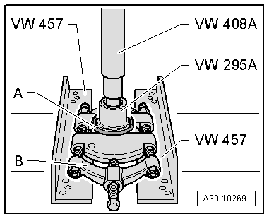
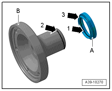
Installation Location of the Protective Ring -A- on the Flange/Driveshaft
- The ridge -arrow 1- on the protective ring -A- must fit into the groove -arrow 2- on the flange -B-. The smaller outer circumference -arrow 3- faces the flange.
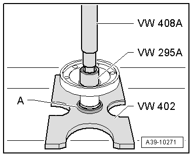
Install the Protective Ring -A- onto the Flange/Driveshaft.
- The protective ring -A- must fit into the groove all around the flange. Refer to → Fig. "Installation Location of the Protective Ring -A- on the Flange/Driveshaft".
Flange Input Shaft Ring, Replacing, 0BE, 0BF
- The ring can only be replaced with the input shaft removed.
Special tools and workshop equipment required
- Bearing/Bushing Installer - Multiple Use -VW295A-
- Press Plate -VW402-
- Press Piece - Rod -VW408A-
- Support Channels -VW457-
- -3-Separating tool 22 to 75 mm, such as Puller - Kukko Quick Action Separating Tool - 12-75mm -17/1-
- Input shaft removed. 0BE (refer to → Chapter "Input Shaft Seal, Replacing, 0BE".) or 0BF (refer to → Chapter "Input Shaft Seal, Replacing, 0BF".)
Remove the Ring -A- from the Flange/Driveshaft
B - Separating Tool - 12-75mm, such as Puller - Kukko Quick Action Separating Tool - 12-75mm -17/1-
Installation Location of the Protective Ring -A- on the Flange/Driveshaft
- The ridge -arrow 1- on the protective ring -A- must fit into the groove -arrow 2- on the flange -B-. The smaller outer circumference -arrow 3- faces the flange.
Install the Protective Ring -A- onto the Flange/Driveshaft
- The protective ring -A- must fit into the groove all around the flange. Refer to → Fig. "Installation Location of the Protective Ring -A- on the Flange/Driveshaft".
Flange/Driveshaft, Replacing, 0BD
- (The rear final drive is removed.)
Special tools and workshop equipment required
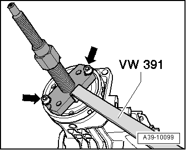
- Puller - Multiple Use -VW391-
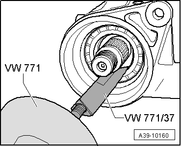
- Slide Hammer Set -VW771-
- Slide Hammer Set - Hook -VW771/37-
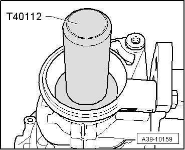
- Seal Installer - Propshaft Flange - T40112-
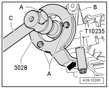
- Retainer - Drive Flange - 3028-
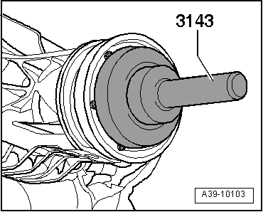
- Seal Installer - Wheel Bearing Seal - 3143-
- Holding Fixture - Gearbox Adapter -T10235-
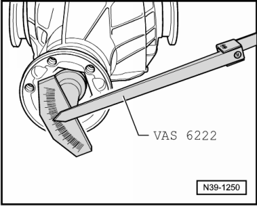
- Friction Gauge - VAS6222-
- Inductive Heater -VAS6414-
- Sealing Grease -G 052 128 A1-
- Locking Fluid - AMV 185 101 A1-
- Three M8 x 25 bolts
- Two M10 x 40 bolts
Pay attention to the general repair information. Refer to → Chapter "Repair Information".
- Remove the rear final drive. Refer to → Chapter "Final Drive, Removing and Installing".
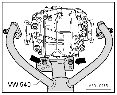
- Secure the rear final drive to the Holding Fixture -VW540- using the bolts (M10 x 40) -arrows-.
- Measure the friction torque before loosening the pinion nut.
- Write down this value.
 Caution
After the seal is replaced, friction torque must be restored to this measured value.
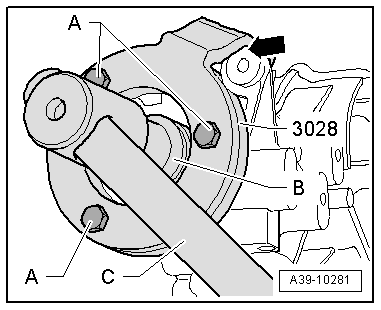
- Secure the Retainer - Drive Flange -3028- to the flange/driveshaft with the bolts -A-.
- Secure the Holding Fixture - Gearbox Adapter -T10235- in the threaded hole below the flange/driveshaft.
- Loosen the pinion nut, at the same time the Retainer - Drive Flange -3028- must be supported on the Holding Fixture - Gearbox Adapter -T10235--arrow-.
-A -Three M 8 x 25 bolts
-B -32 mm Socket
-C -Toggle
- Secure the Puller - Multiple Use -VW391- using the Two bolts M 8 x 25 -arrows-.
- Remove the flange/driveshaft.
- Remove the shaft seal.
- Clean the threads on the drive pinion.
- Coat outer edge of the seal with gear oil.
- Fill the space between the sealing/dust lip halfway with Sealing Grease -G 052 128 A1-.
- Drive in new shaft seal as far as stop without tilting it.
- Warm the flange/driveshaft to approximately 80 ℃ (176 ºF) using an Inductive Heater -VAS6414-.
- Install the new flange/driveshaft.
- Coat the threads on the new nut with Locking Fluid - AMV 185 101 A1-.
- Secure the Retainer - Drive Flange -3028- to the flange/driveshaft with the bolts -A-.
- When tightening the pinion nut, the Retainer - Drive Flange -3028- must be supported on the housing brace -arrow-.
-A -Three M 8 x 25 bolts
-B -32 mm Socket
-C -Toggle
Caution
Increase the torque slowly and read the friction torque several times. The friction torque must not exceed the value that was measured before the removal, otherwise the rear final drive must be replaced.
- Tighten the new drive pinion nut just enough until the measured friction torque is reached before removing.
- Install the rear final drive. Refer to → Chapter "Final Drive, Removing and Installing".
- Check the gear oil in rear final drive. Refer to → Chapter "Gear Oil, Checking Level, 0BD".
