Audi A6 Typ 4G: General, Technical data
Rear Final Drive Identification 0BF and 0BE
The "Rear Final Drive 0BF" is installed in Audi A4 from MY 2008, Audi A6 Coup from MY 2008, Audi A5 Cabriolet from 2009, Audi A6 from MY 2011, Audi A7 from MY 2011, and Audi A8 from My 2010.
Allocation to the following transmissions:
- 6-Speed Manual Transmission 0B2 AWD
- 6-Speed Manual Transmission 0B4 AWD
- 7-Speed S tronic Transmission 0B5 AWD
- Automatic Transmission 0B6 AWD
- 8-Speed Automatic Transmission 0BK AWD
The "Rear Final Drive 0BE" is an enhanced version of the "0BF" and is installed exclusively with the V8 TDI Engine in the Audi A8 from MY 2010.
Allocation to the following transmission:
- 8-Speed Automatic Transmission 0BL AWD
Rear Final Drive Allocation
- Refer to → Chapter "Codes, Transmission Allocations, Ratios, Capacities, Audi A4 from MY 2008"
- Refer to → Chapter "Codes, Transmission Allocations, Ratios and Capacities, Audi A5 Coupe from MY 2008"
- Refer to → Chapter "Codes, Transmission Allocations, Ratios and Capacities, Audi A5 Sportback from MY 2010"
- Refer to → Chapter "Codes, Transmission Allocations, Ratios and Capacities, Audi A5 Cabriolet from MY 2009"
- Refer to → Chapter "Codes, Transmission Allocations, Ratios and Capacities for Audi A6 from MY 2011"
- Refer to → Chapter "Codes, Transmission Allocations, Ratios and Capacities for Audi A7 from MY 2011"
- Refer to → Chapter "Codes, Transmission Allocations, Ratios and Capacities, Audi A8 from MY 2010"
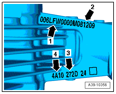
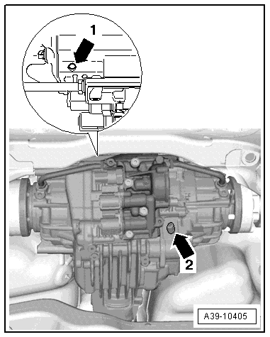
Layout on Rear Final Drive
Clutch class -arrow 1-.
Engine code and production date -arrow 2-
 Note
Note
The way to recognize the rear final drive "0BF and 0BE" is the hydraulic control unit with the side chambers.
- -Arrow 1- code -LFW-
- -Arrow 2- Rear final drive build dates
.png)
- -Arrow 3- Classification (classification of the clutch friction values) for the right clutch. Example: -272D-
- -Arrow 4- Classification (classification of the clutch friction values) for the left clutch. Example: -4A10-
Additional data can be ignored.
Note
When the rear final drive is replaced, not only the final drive code but also the PR number and the vehicle engine code must be verified in the Parts Catalog. This is the only way to assure the correct allocation.
Codes, Transmission Allocation, Ratios and Capacities
Codes, Transmission Allocations, Ratios, Capacities, Audi A4 from MY 2008v
Refer to the Parts Catalog for the following information.
- Production date
- The engine, manual transmission and automatic transmission allocation using the code letters and the PR numbers
.png)
.png)
Codes, Transmission Allocations, Ratios and Capacities, Audi A5 Coupe from MY 2008
Refer to the Parts Catalog for the following information.
- Production date
- The engine, manual transmission and automatic transmission allocation using the code letters and the PR numbers
 Caution
Gear oil and ATF change Audi RS5
- The RS5 gear oil and ATF must be changed.
- RS5 change interval. Refer to the →Maintenance Intervals; Rep. Gr.03.
- For all other vehicles there is no change interval.
.png)
.png)
Codes, Transmission Allocations, Ratios and Capacities, Audi A5 Sportback from MY 2010
.png)
Codes, Transmission Allocations, Ratios and Capacities, Audi A5 Cabriolet from MY 2009v
Refer to the Parts Catalog for the following information.
- Production date
- The engine, manual transmission and automatic transmission allocation using the code letters and the PR numbers
.png)
Codes, Transmission Allocations, Ratios and Capacities for Audi A6 from MY 2011
- Production date
- The engine, manual transmission and automatic transmission allocation using the code letters and the PR numbers
.png)
Codes, Transmission Allocations, Ratios and Capacities for Audi A7 from MY 2011
Refer to the Parts Catalog for the following information.
- Production date
- The engine, manual transmission and automatic transmission allocation using the code letters and the PR numbers
.png)
Codes, Transmission Allocations, Ratios and Capacities, Audi A8 from MY 2010
Note
- In the Audi A8 from My 2010 two different versions of rear final drive are installed, rear final drive 0BF or 0BE.
- The rear final drive 0BE is an enhanced version and is installed exclusively with the V8 TDI Engine.
Refer to the Parts Catalog for the following information.
- Production date
- The engine, manual transmission and automatic transmission allocation using the code letters and the PR numbers
.png)
Overview - Powertrain
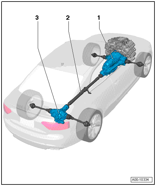
1 - Transmission
2 - Driveshaft
3 - Rear Final Drive
General Repair Information
 WARNING
Incorrect repairs to the rear final 0BF and 0BE could cause the final drive to malfunction.
- Testing, assembling and servicing must be performed by qualified personnel only.
- Always follow all the safety precautions and test procedures. Refer to → Chapter "Safety Precautions and Test Procedures".
- The highest level of care and cleanliness along with tools that function properly are required to ensure a proper and successful transmission repair. Of course the general safety precautions also apply when carrying out repair work.
- A number of generally applicable instructions for individual repair procedures, which are otherwise mentioned at various points in the Repair Manual, are summarized here under the topic "Components". Refer to → Chapter "Components". They apply to this repair manual.
Safety Precautions and Test Procedures
WARNING
Incorrect repairs to the rear final 0BF and 0BE could cause the final drive to malfunction.
Testing, assembling and servicing must be performed by qualified personnel only.
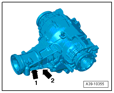
Correct Oil Level
- Make sure the rear final drive is filled to specified oil capacity. Refer to → Chapter "Codes, Transmission Allocation, Ratios and Capacities".
- Fix any leaks on the rear final drive, for example, on the sealing surfaces or the seals. The oil can leak out through the holes between the left -arrow 1- or right -arrow 2- chamber and the rear final drive.
Caution
Rear final drive malfunction.
- Do not drive the rear final drive if there are leaks or insufficient oil.
- Leaks on the rear final drive must be corrected.
- Fill the ATF and/or gear oil if the levels are low.
- Only use ATF or gear oil available as a replacement part. Refer to the Parts Catalog.
- If the leaks cannot be repaired, then the rear final drive must be replaced.
Rear Final Drive Performance
WARNING
Transmission control malfunction.
Always maintain all specifications when replacing transmission components. Only by doing so assures the performance and the response characteristics of the rear final drive 0BF and 0BE.
Replacing Transmission Components
- When replacing the All Wheel Drive Control Module -J492-, the adaptation values for the transmission mount (for example clutch wear, oil aging) must be transmitted with the Vehicle Diagnostic Tester otherwise the performance of the rear final drive will be impaired.
- When replacing a chamber or the complete rear final drive, the clutch classification must be entered again in the All Wheel Drive Control Module -J492- using the Vehicle Diagnostic Tester. If the clutch classification is not performed in the All Wheel Drive Control Module -J492- then the rear final drive performance will be impaired. When replacing a chamber, the classification identification on the rear final drive housing must be made unrecognizable. The identification of the new classification is made on the new chamber housing.
- Do not place the removed rear final drive on any of the components from the hydraulic control unit (for example, clutch valves). This could damage the components.
Replacing the Oil Pressure/Temperature Sensor -G437- and/or Oil Pressure/Temperature Sensor 2 -G640-.
- The identity of the sensor in the All Wheel Drive Control Module -J492- must be adapted using the Vehicle Diagnostic Tester after replacing the Oil Pressure/Temperature Sensor -G437- or the Oil Pressure/Temperature Sensor 2 -G640-.
- Do not replace both the Oil Pressure/Temperature Sensor -G437- and Oil Pressure/Temperature Sensor 2 -G640- at the same time because a valid sensor identity is needed for the rear final drive classification to the All Wheel Drive Control Module -J492-. If the both sensors are replaced at the same time, the All Wheel Drive Control Module -J492- will interpret this as the rear final drive is being replaced. By doing this, adaptation values in the control module will be erased and the performance of the rear final drive will be impaired.
- If both the Oil Pressure/Temperature Sensor -G437- and the -G640- must be replaced due to mechanical damage, for example, if the connector housing gets damaged, then this must be performed in two steps. After replacing the first sensor, the identity of the must be adapted in the All Wheel Drive Control Module -J492- using the Vehicle Diagnostic Tester. Do the same for the second sensor.
- If both the Oil Pressure/Temperature Sensor -G437- and Oil Pressure/Temperature Sensor 2 -G640- must be replaced at the same time due to an electrical fault, then the clutch classification must be entered into the All Wheel Drive Control Module -J492- using the Vehicle Diagnostic Tester. Additionally the ATF must be changed. Refer to → Chapter "ATF on Rear Final Drive 0BF and 0BE, Draining".
Torque Displacement, Checking
After the following work the function 22- Checking the torque displacement must be performed:
- Working on the rear final drive wiring
- Working on the valves: All Wheel Drive Clutch Valve -N445- and All Wheel Drive Clutch Valve 2 -N446-.
- Working on the hydraulic control unit
Vehicle Lift Mode, Vehicles with Air Suspension
Activate the lift mode before lifting the vehicle on a two-column shop hoist (when there is no weight on the wheels).
Special Tools
Refer to the Special Tools Catalog for the complete list of special tools used in this repair manual.
Components
Rear Final Drive
- Allocate bolts and other components according to final drive code using the Parts Catalog
- When replacing the rear final drive, check the gear oil level (refer to → Chapter "Gear Oil Level in Rear Final Drive 0BF and 0BE, Checking") and the ATF level (refer to → Chapter "ATF Level in Rear Final Drive 0BF and 0BE, Checking") in the final drive.
- Capacities and specifications. Refer to → Chapter "Codes, Transmission Allocation, Ratios and Capacities".
- Clean the contact surfaces when installing brackets and waxed components. Contact surfaces must be free of wax and grease.
- Thoroughly clean the connection points and the surrounding area before loosening.
ATF and Gear Oil
Rear final drive 0BF and 0BE works with separated oil chambers for the ATF and gear oil.
- For the hydraulics (hydraulic control unit and left and right chambers) use only ATF which can be obtained as replacement part. Refer to Parts Catalog.
- For the final drive (gear set, differential) use only the gear oil which can be obtained as replacement part. Refer to the Parts Catalog.
- Other ATF or gear oil can cause function problems.
Caution
Gear oil and ATF change Audi RS5
- The RS5 gear oil and ATF must be changed.
- RS5 change interval. Refer to the →Maintenance Intervals; Rep. Gr.03.
- For all other vehicles there is no change interval.
Oil, Environmental and Disposal Regulations
- Handle ATF, transmission fluid and other oils carefully.
- Dispose of drained fluid properly.
- Follow the legal environmental and disposal regulations.
- Be sure to read the instructions on the fluid containers.
Sealant
- Thoroughly clean the housing separating surfaces before applying the sealing compound.
- Apply Sealing Compound -D 176 501 A1- evenly and not too thick.
- Keep the sealant from getting into the bleed holes or into the oil channels.
Shaft Seals
- Lightly coat the shaft seal on the outer diameter with oil before installing.
- The open side on the shaft seals faces the fluid to be sealed off.
- After replacing any of the shaft seals, check the gear oil level (refer to → Chapter "Gear Oil Level in Rear Final Drive 0BF and 0BE, Checking") or the ATF level (refer to → Chapter "ATF Level in Rear Final Drive 0BF and 0BE, Checking") in the final drive.
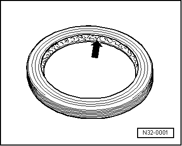
Shaft Seal for the Flange/Driveshaft
- Fill the space between the sealing lips -arrow- halfway with Sealing Grease -G 052 128 A1-.
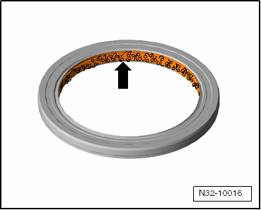
Flange Shaft Seals
- Coat the space between the sealing lips -arrow- with ATF.
O-Rings, Gaskets and Seals
- O-rings, gaskets and seals must always be replaced.
- After removing the seals, examine the contact surface on the housing or shaft for burrs resulting from removal or for other signs of damage.
- Thoroughly clean the housing separating surfaces before assembling.
- Lightly lubricate the O-rings before inserting to prevent the rings from being crushed during assembly.
- After replacing any of the gaskets, seal and O-rings, check the gear oil level (refer to → Chapter "Gear Oil Level in Rear Final Drive 0BF and 0BE, Checking") or the ATF level (refer to → Chapter "ATF Level in Rear Final Drive 0BF and 0BE, Checking") in the final drive.
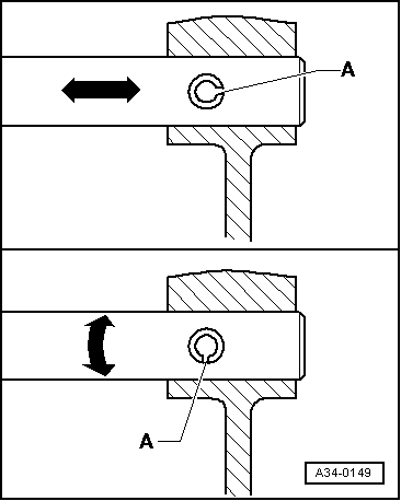
Retainers
- Do not stretch the circlips.
- Always replace damaged or stretched circlips.
- The circlips must rest at the bottom of the groove.
- Replace the adapter sleeves. Installation position: the slot -A- should align with the line of force -arrow-.
Bolts and Nuts
- Always loosen or tighten bolts and nuts on covers and housings diagonally.
- Parts which are particularly sensitive must not be tilted and must be loosen or tighten diagonally in stages.
- The tightening specifications given apply to unoiled bolts and nuts.
- Always replace self-locking bolts and nuts.
- Clean the threads of bolts that were applied with locking fluid using a wire brush (does not apply to driveshaft bolts: these must be replaced). Then insert the bolts with Locking Fluid -AMV 185 101 A1-.
- If self-locking bolts were installed or if bolts were installed with locking fluid, then the threaded holes must be cleaned, for example with a thread tap. Otherwise there is the risk that the bolts could break off the next time they are removed.