Audi A6 Typ 4G: Front Bumper Cover, Removing and Installing
Bumper Cover, Removing and Installing
 Caution
On vehicles with distance regulation (ACC), note the following.
If the bumper is removed and re-installed or changes are made to "ACC" bracket, distance regulation adjustment must be carried out.
Note the following on vehicles with an Night Vision System Camera -R212-.
If the bumper was removed and then installed again, or if changes were made to the radiator grille, then it is necessary to calibrate the Night Vision System Camera -R212-.
For vehicles with Front Peripheral Camera -R243-, observe the following.
If the bumper was removed and then installed again, or if changes were made to the radiator grille, then it is necessary to calibrate the Front Peripheral Camera -R243-.
Special tools and workshop equipment required
- Hose Clamps - Up To 25 mm -3094-
- Engine Bung Set -VAS 6122-
Removing
- Only loosen the front wheel housing liner in the area on the bumper (do not remove). Refer to → Chapter "Front Wheel Housing Liner, Removing and Installing".
- Remove the wheel spoiler. Refer to → Chapter "Front Wheel Spoiler, Removing and Installing".
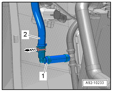
- Place a drip tray under the separating point for the windshield washer fluid hose.
- Clamp off the windshield washer fluid hose -2- with Hose Clamps - Up To 25mm - 3094-.
- Pull the clip arrow and disconnect the windshield washer fluid hose for the headlamp washer system -arrow-.
 Note
Note
Depending on the version the washer fluid hose release button can be installed on the connecting piece.
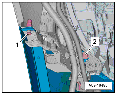
- Close the hose coupling -1- with clean plus from the Engine Bung Set -VAS 6122-.
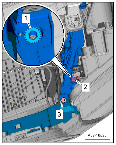
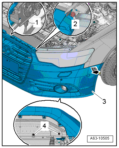
- Remove the bolts -1 and 2-.
- Audi RD6: remove the bolt -arrow-.
- Remove the bolts -4-.
- Remove the lock carrier cover. Refer to → Chapter "Lock Carrier Cover, Removing and Installing".
- Remove the bolt -2-.
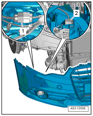
- If the vehicle has a camera for the infrared system, disconnect the connector -1-.
- Disconnect the connector if the vehicle has a garage door opener control module.
- Disconnect the connector for vehicles with the front environmental camera.
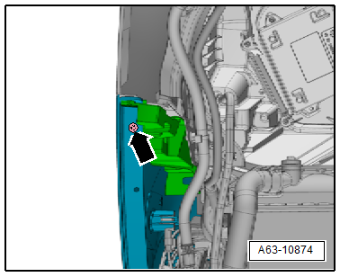
- Disengage the side bolster -3- from the front side panel -arrow- and remove the bumper cover with a second technician.
Note
If the side piece from the side panel cannot be disengaged the front center bumper cover mount must be loosened. Refer to → Chapter "Front Bumper Cover Mount, Removing and Installing".
- Disconnect the connector -1-.
- Through MY 2014 the connector is on the right side.
- From MY 2015 the connector is on the left side.
- Disconnect the connector if the vehicle has distance regulation control module (ACC) -2-.
Installing
Install in reverse order of removal. Note the following:
- Check the gap dimensions. Refer to → Chapter "Front Bumper Cover Gap Dimensions".
- If the vehicle has a distance regulation control module (ACC), then calibrate the control modules. Refer to → Suspension, Wheels, Steering; Rep. Gr.44; Adaptive Cruise Control (ACC); Adaptive Cruise Control (ACC), Calibrating.
- If the vehicle has a night vision system camera, then calibrate the Night Vision System Camera -R212-. Refer to → Communication; Rep. Gr.91; Infrared System.
- For vehicles with the front environmental camera, the Front Peripheral Camera -- needs to be recalibrated. Refer to → Communication; Rep. Gr.91; Peripheral Camera; Component Location Overview - Peripheral Camera.
→ Vehicle Diagnostic Tester in "Guided Fault Finding" or "Guided Functions" must be calibrated under the following conditions:
- The camera or control module has been installed or replaced.
- The front bumper cover was damaged, for example, by a cement parking stop.
- The front bumper cover was removed and installed.
- The radiator grille was removed and installed.
- The rear axle was adjusted.
- Work was done to the suspension.
- The entry "no or incorrect basic setting/adaptation" is stored in the DTC memory.
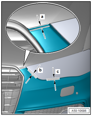
Front Bumper Cover Gap Dimensions
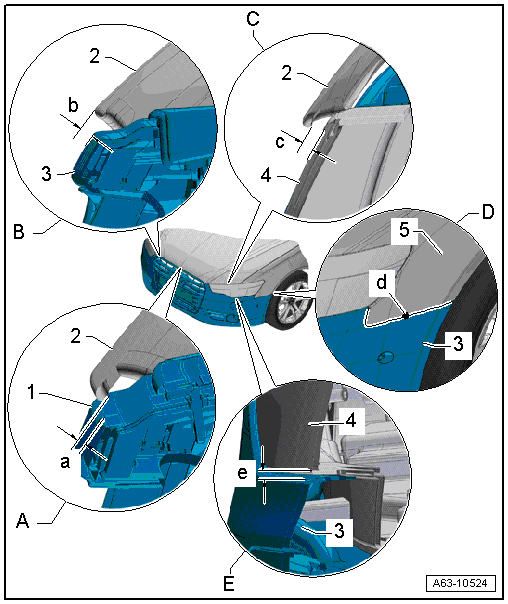
A - Hood to Radiator Grille
- Gap dimension -a- = 4.5 mm
-1- Radiator grille
-2- Hood
- Adjusting. Refer to → Chapter "Front Bumper Cover, Adjusting".
B - Hood to Front Bumper Cover
- Gap dimension -b- = 3.5 mm
-2- Hood
-3- Bumper cover
- Adjusting. Refer to → Chapter "Front Bumper Cover, Adjusting".
C - Hood to Headlamp Housing
- Gap dimension -c- = 5.9 to 5.3 mm
-2- Hood
-4- Headlamp housing
D - Front Bumper Cover to the Front Fender
- Gap dimension -d- = zero gap
-3- Bumper cover
-5- Front fender
E - Front Bumper Cover to the Headlamp Housing
- Gap dimension -e- = 2.0 mm
-3- Bumper cover
-4- Headlamp housing
Front Bumper Cover, Adjusting
Special tools and workshop equipment required
- Adjusting Tool -T40281-
Procedure
- Gap dimensions. Refer to → Chapter "Front Bumper Cover Gap Dimensions".
- Tightening Specifications. Refer to → Chapter "Overview - Bumper Cover".
- Remove the lock carrier cover. Refer to → Chapter "Lock Carrier Cover, Removing and Installing".
Height Adjustment:
- Remove the bolt -4-.
- Loosen or tighten the adjusting nut -5- in stages using the Adjusting Tool - T40281--arrows- until the gap dimension of the bumper cover -2- to the hood -3- and headlamp -1- is reached.
- Dimension -a- = 4.5 mm
- Dimension -b- = 2.5 mm
- Dimension -c- = 2.0 mm
- Tighten the bolt to -4- to 8 Nm.
- Check the gap dimensions again and repeat the adjustment as first described, if needed.
- Check the gap dimension and repeat the adjustment if necessary.
Longitudinal Setting:
- Loosen the bolt -3-.
- Adjust the front bumper cover in the longitudinal direction.
- Tighten the bolt -3- to the tightening specification. Refer to -item 11-.
- Check the gap dimension. Refer to → Chapter "Front Bumper Cover Gap Dimensions", and repeat the adjustment if necessary.