Audi A6 Typ 4G: Impact Member, Removing and Installing
Impact Member, Removing and Installing
Removing
 Note
Note
When installing, bring all cable ties back to same positions.
- Remove the front bumper cover. Refer to → Chapter "Bumper Cover, Removing and Installing".
- Remove the headlamp housing. Refer to → Electrical Equipment; Rep. Gr.94; Headlamp; Headlamp, Removing and Installing.
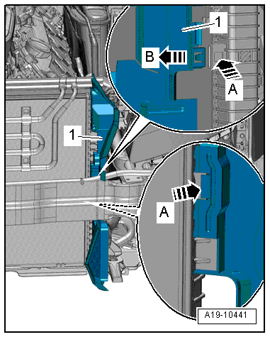
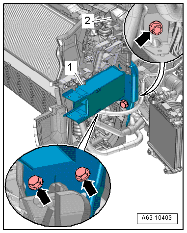
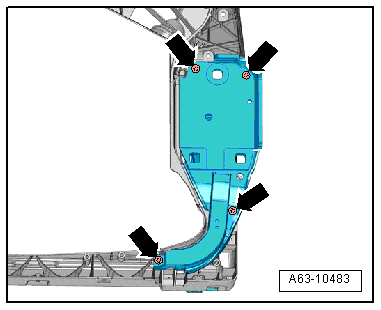
- If equipped, open the tabs -A arrows- and remove the air guide -1--B arrow-.
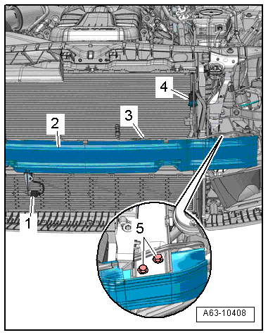
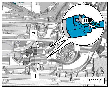
- Disconnect the connector from the Outside Air Temperature Sensor -G17--item 1- and A/C Pressure/Temperature Sensor -G395--item 4- and free up the wiring harness -3-.
- Remove the nuts and bolts -5- upward.
- Remove the impact bar -2- from the mounts.
Note
Pry the impact bar out of the mounts if it is not easy to remove.
- If the impact member is being replaced, then remove the bracket for the Outside Air Temperature Sensor -G17-. Refer to → Chapter "Outside Air Temperature Sensor -G17- Bracket, Removing and Installing".
Installing
Install in reverse order of removal.
Connecting Brace, Removing and Installing
Special tools and workshop equipment required
- Drill
- Drill 5 mm diameter.
Removing
- Remove the bumper cover mount. Refer to → Chapter "Bumper Cover Mount, Removing and Installing, Vehicles through MY 2014".
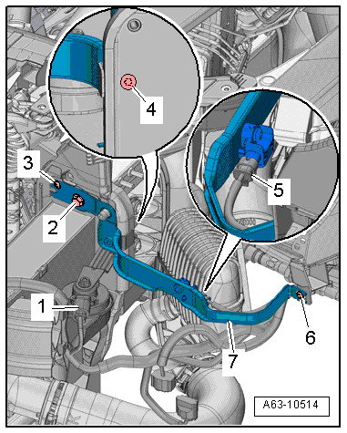
- Disconnect the connector -5- to the front airbag crash sensor. Pay attention to the Safety Precautions. Refer to → Body Interior; Rep. Gr.00; Safety Precautions; Pyrotechnic Components Safety Precautions.
- Disconnect the connector -1- from the horn.
- Remove the bolt -4- and the horn bracket.
- Drill out the blind rivet head -3- and strike the rivet shaft out.
- Loosen the bolt -6-, remove the bolt -2- and remove the connecting brace -7-.
Installing
Install in reverse order of removal.
Left Impact Member Mount, Removing and Installing
Removing
- Remove the front noise insulation. Refer to → Chapter "Front Noise Insulation, Removing and Installing".
- Remove the left front wheel spoiler. Refer to → Chapter "Front Wheel Housing Liner, Removing and Installing".
- Remove the impact member. Refer to → Chapter "Impact Member, Removing and Installing".
- Remove the connecting brace. Refer to → Chapter "Connecting Brace, Removing and Installing".
- On vehicles with a gasoline engine, move the left cooler for charge air cooling circuit with the coolant hoses still connected to the rear. Refer to → Engine Mechanical, Fuel Injection and Ignition; Rep. Gr.19; Radiator/Coolant Fan; Charge Air Cooling Circuit Radiator, Removing and Installing.
- On vehicles with 3.0L TDI engine (EA 897 Gen I) remove the charge air cooler. Refer to → Engine Mechanical, Fuel Injection and Glow Plug; Rep. Gr.21; Charge Air System; Charge Air Cooler, Removing and Installing.
- If equipped loosen the crossmember. Refer to → Engine Mechanical, Fuel Injection and Ignition; Rep. Gr.10; Subframe Mount; Overview - Subframe Mount.
- If equipped, remove the horn bracket. Refer to → Electrical Equipment; Rep. Gr.90; Horn; Overview - Horn.
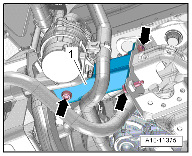
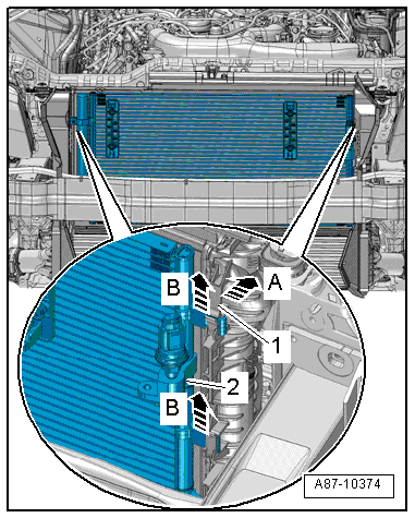
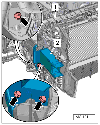
- Remove the bolts -arrows-.
- Have a second technician open the clamps -1- in direction of -arrow A- and remove the condenser -2- from the mounts on the radiator -B arrows-.
 Caution
There is a risk of damaging the condenser and refrigerant lines and hoses.
Do not bend, twist or stretch the refrigerant lines and hoses.
- Move the condenser with the lines still connected, forward and then to the side and then secure it.
- Mark the installation position of the mount to the lock carrier for installation later.
- Drill out the blind rivet and strike out the rivet shaft.
- Remove the bolts -arrows-.
- Move the lock carrier -2- slightly to the front and remove the impact member mount -1- to the left.
Installing
Install in reverse order of removal. Note the following:
- Tighten the impact member mount according to the marking made during removal.
- To rivet the bracket on the lock carrier, the radiator and fan shroud must be removed. Refer to → Rep. Gr.19; Radiator/Coolant Fan; Radiator, Removing and Installing.
Right Impact Member Mount, Removing and Installing
Removing
- Remove the front noise insulation. Refer to → Chapter "Front Noise Insulation, Removing and Installing".
- Remove the right wheel spoiler. Refer to → Chapter "Front Wheel Spoiler, Removing and Installing".
- Remove the impact member. Refer to → Chapter "Impact Member, Removing and Installing".
- Remove the connecting brace. Refer to → Chapter "Connecting Brace, Removing and Installing".
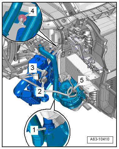
- Disconnect the connector -5- on the horn and remove the horn bracket. Refer to → Electrical Equipment; Rep. Gr.90; Horn; High Tone Horn H2/Low Tone Horn H7, Removing and Installing.
- If the vehicle has an auxiliary heater, remove the nut -4- and free up the coolant lines.
- Press the release, push the connector down and then free up the connectors -2 and 3- on the brackets.
- If the vehicle has a secondary air injection pump motor, then press the release button and remove the hose from the secondary air injection pump -1-.
- On vehicles with 3.0L TDI engine (EA 897 Gen I) remove the charge air cooler. Refer to → Rep. Gr.21; Charge Air System; Charge Air Cooler, Removing and Installing.
- If equipped loosen the crossmember. Refer to → Engine Mechanical, Fuel Injection and Ignition; Rep. Gr.10; Subframe Mount; Overview - Subframe Mount.
- Push the retainer back -arrow-, press the release down and disconnect the coolant fan connectors -1- and -2-, if applicable.
- Remove the bolts -arrows-.
- Mark the installation position of the mount to the lock carrier for installation later.
- Drill out the blind rivet and strike out the rivet shaft.
- Remove the bolts -arrows-.
- Move the lock carrier -1- slightly to the front and remove the impact member mount -2- to the right.
Installing
Install in reverse order of removal. Note the following:
- Tighten the impact member mount according to the marking made during removal.
- To rivet the bracket on the lock carrier, the radiator and fan shroud must be removed. Refer to → Rep. Gr.19; Radiator/Coolant Fan; Radiator, Removing and Installing.
Lower Front Longitudinal Member, Removing and Installing
Removing
- Remove the front bumper cover. Refer to → Chapter "Bumper Cover, Removing and Installing".
- Remove the wheel spoiler. Refer to → Chapter "Front Wheel Spoiler, Removing and Installing".
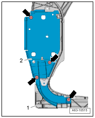
- Remove the bolts -arrows- and the front lower longitudinal member -1-.
Installing
Install in reverse order of removal.