Audi A6 Typ 4G: Front Seat, Removing and Installing
Front Seat, Removing and Installing
Special tools and workshop equipment required
- Trim Removal Wedge -3409-
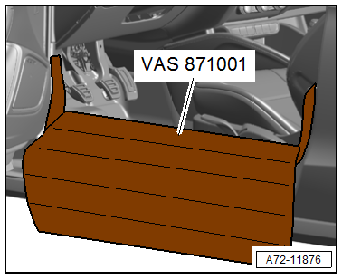
- Universal Vehicle Protector -VAS871001-
Removing
 WARNING
- Follow all Safety Precautions when working with pyrotechnic components. Refer to → Chapter "Pyrotechnic Components Safety Precautions".
- Before handling pyrotechnic components (for example, disconnecting the connector), the person handling it must "discharge static electricity". This can be done by touching the door striker, for example.
- Push the headrest into the lowest position.
- Move the front seat all the way to the rear and then into its highest position.
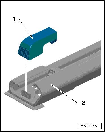
- Pry off the front spindle cover -1- from the seat rail cover -2- and the forward/back adjustment spindle using the Trim Removal Wedge -3409-.
- Move the front seat all the way forward/up.
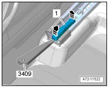
- Pry the rear spindle cover -1- off of the seat rail cover and the seat rail bolt using the Trim Removal Wedge -3409- in direction of -arrows-.
- Remove the front belt end fitting. Refer to → Chapter "Front Belt End Fitting, Removing and Installing".
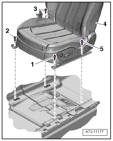
- Remove the rear bolts -3 and 5- in the back on the seat rail.
- Move the front seat -4- to the rear and then into its highest position.
- Remove the front bolts -1 and 2- from the seat rail.
- Disconnect the battery Ground (GND) cable with the ignition turned on. Refer to → Electrical Equipment; Rep. Gr.27; Battery; Battery, Disconnecting and Connecting.
WARNING
Before handling pyrotechnic components (for example, disconnecting the connector), the person handling it must "discharge static electricity". This can be done by touching the door striker, for example.
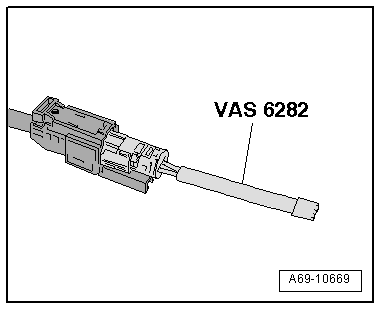
- Connect Airbag Lockout Adapter -VAS6282- to the side airbag harness connector. Refer to → Chapter "Airbag Adapter, Connecting and Disconnecting".
- Disconnect the connectors.
- To protect the sill panel before prying out the front seat install the Universal Vehicle Protector -VAS871001- as shown in the illustration.
- Remove the front seat from the vehicle with a second technician.
Installing
WARNING
- Follow all Safety Precautions when working with pyrotechnic components. Refer to → Chapter "Pyrotechnic Components Safety Precautions".
- Before handling pyrotechnic components (for example, connecting the connector), the person handling it must "discharge static electricity". This can be done by touching the door striker, for example.
Install in reverse order of removal. Note the following:
- Attach the connectors and remove the Airbag Lockout Adapter -VAS6282- only after installing the front seat. Refer to → Chapter "Airbag Adapter, Connecting and Disconnecting".
 Note
Note
Make sure the connectors are installed correctly and are secure.
- Align the front seat -4- inside the vehicle and tighten the front bolts -1 and 2- on the seat rail hand-tight only.
WARNING
Ignition must be on when connecting battery. If pyrotechnic components (for example, airbag, belt tensioner) are not repaired correctly, they may deploy unintentionally after connecting battery. There must not be anyone inside the vehicle when connecting the battery.
DANGER!
When working on vehicles with the ignition already switched on or that are ready to drive there is a danger of the engine starting unexpectedly and of being poisoned by gas in enclosed areas. Risk of body parts and/or clothing being clamped or pulled.
Perform the following before switching on the ignition:
- Move the selector lever into P.
- Activate the parking brake
- Turn off the ignition.
- Open the hood
- Connect the charger, such as the Battery Charger -VAS5095A- to the jump start of the 12V vehicle electrical system.
- Turn on the ignition.
- Connect the battery GND cable with the ignition turned on. Refer to → Electrical Equipment; Rep. Gr.27; Battery; Battery, Disconnecting and Connecting.
- Move the front seat all the way forward/up.
- Mount the bolts -3 and 5- on the seat rail and tighten them.
- Move the front seat all the way to the rear and then into its highest position.
- Tighten front bolts.
- Airbag Lockout Adapter -VAS6282-, removing and installing. Refer to → Chapter "Airbag Adapter, Connecting and Disconnecting".
Note
If the Airbag Indicator Lamp -K75- indicates a fault, check the Diagnostic Trouble Code (DTC) memory, erase it and check it again. Refer to Vehicle Diagnostic Tester.
Installation notes, for example tightening specifications, replacing components. Refer to → Chapter "Overview - Front Seat".
Front Seat with Faulty Seat Forward/Back Adjustment Motor or Faulty Control Module, Removing
Special tools and workshop equipment required
- Universal Vehicle Protector -VAS871001-
Driver Seat Forward/Back Adjustment Motor -V28-/Front Passenger Seat Forward/Back Adjustment Motor -V31- or Memory Seat/Steering Column Adjustment Control Module -J136-/Front Passenger Memory Seat Control Module -J521-, checking
WARNING
- Follow all Safety Precautions when working with pyrotechnic components. Refer to → Chapter "Pyrotechnic Components Safety Precautions".
- Before handling pyrotechnic components (for example, disconnecting the connector), the person handling it must "discharge static electricity". This can be done by touching the door striker, for example.
- Move the front seat all the way up.
Note
Check electrical and electronic components and wires before removing front seat further to avoid unnecessary repair costs.
- Perform the following tests:
- Check the fuse. Refer to → Wiring diagrams, Troubleshooting & Component locations.
- Check the voltage at the connector station and perform fault finding if necessary. Refer to → Wiring diagrams, Troubleshooting & Component locations.
- Check the voltage to the control module. Refer to → Wiring diagrams, Troubleshooting & Component locations.
- Check the voltage to the seat forward/back adjustment motor. Refer to → Wiring diagrams, Troubleshooting & Component locations.
- Replace the fuse if faulty. Refer to → Wiring diagrams, Troubleshooting & Component locations.
- If there is no voltage at the connector station, repair or replace the wire. Refer to → Wiring diagrams, Troubleshooting & Component locations.
- Replace the lower seat frame together with seat forward/back adjustment motor if the seat forward/back adjustment motor is faulty. Refer to → Chapter "Lower Seat Frame/Forward/Back Adjustment Motor, Removing and Installing".
- If the control module is faulty: replace the Memory Seat/Steering Column Adjustment Control Module -J136-/Front Passenger Memory Seat Control Module -J521-. Refer to → Chapter "Seat/Steering Column Adjustment Control Module with Memory Function, Removing and Installing".
Removing with faulty Driver Seat Forward/Back Adjustment Motor -V28-/Front Passenger Seat Forward/Back Adjustment Motor -V31-
WARNING
Before handling pyrotechnic components (for example, disconnecting the connector), the person handling it must "discharge static electricity". This can be done by touching the door striker, for example.
- Disconnect the battery GNDcable with the ignition turned on. Refer to → Electrical Equipment; Rep. Gr.27; Battery; Battery, Disconnecting and Connecting.
- Remove the front belt end fitting. Refer to → Chapter "Front Belt End Fitting, Removing and Installing".
- Connect Airbag Lockout Adapter -VAS6282- to the side airbag harness connector. Refer to → Chapter "Airbag Adapter, Connecting and Disconnecting".
- Disconnect the connectors.
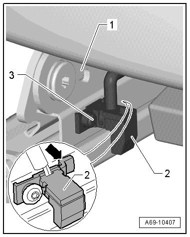
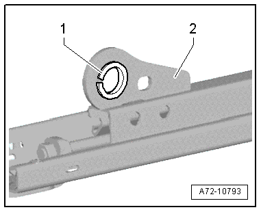
- Remove the bolt -3-.
- Detach the seat position sensor -2- at the hooks -arrow- from the seat pan lower frame -1-.
- Unclip the wire from the lower seat frame and set aside.
- Disconnect the connector on the seat forward/back adjustment motor.
- Remove modular wire routing bracket on the seat pan lower frame.
- Disconnect the connector from the front seat belt latch
Standard Seat/Sport Seat/Super Sport Seat
 Caution
Danger of damaging the threaded holes or the bushing in the bearing points (connecting upper/lower frame).
A second technician must be pushing down on the seat backrest when removing the following bolts.
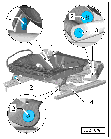
There is a risk of damaging the threads on the bolt -3-.
The bolt on the adjusting spindle has left-hand threads.
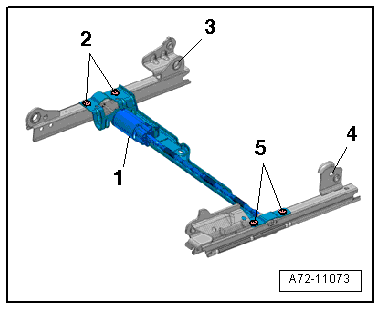
- Remove the bolt -3-.
- Remove the bolts -2-.
- With a second technician, detach the upper seat frame -1- from the lower frame -4- and remove from the vehicle.
Note
The seat pan is shown without the cushion, cover and seat backrest.
Multi-Contour Seat
Caution
Danger of damaging the threaded holes or the bushing in the bearing points (connecting upper/lower frame).
A second technician must be pushing down on the seat backrest when removing the following bolts.
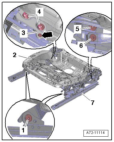
There is a risk of damaging the threads on the bolt -6-.
The bolt on the adjusting spindle has left-hand threads.
- Remove the bolt -6-.
- Remove the bolts -4-.
- Detach the retaining plate -3- on the seat pan lower frame -arrow- and remove.
- Remove the bolts -1 and 5-.
- With a second technician, disengage the upper seat frame -2- from the lower frame -7- and remove from the vehicle.
Note
The seat pan is shown without the cushion, cover and seat backrest.
Procedure for All Seat Versions
Caution
Risk of damaging the bushings -1- in the bearing points -2- (upper/lower frame bolted connection).
- The bushings cannot be replaced with shop materials.
- If the bushings are damaged, the corresponding assembly parts must be replaced.
- Remove accessible bolts for the seat rails on the console.
Note
For reasons of clarity, the surrounding area is not shown.
- Remove the bolts -2 and 5- and remove the seat forward/back adjuster motor -1- and bracket.
- Slide the seat rail -3 and 4- back and forth until the bolt is accessible.
- Remove the screws and the seat rail.
- Replace the seat pan lower frame together with seat forward/back adjustment motor. Refer to → Chapter "Lower Seat Frame/Forward/Back Adjustment Motor, Removing and Installing".
Removing with a faulty Memory Seat/Steering Column Adjustment Control Module -J136-/Front Passenger Memory Seat Control Module -J521-
WARNING
- Follow all Safety Precautions when working with pyrotechnic components. Refer to → Chapter "Pyrotechnic Components Safety Precautions".
- Before handling pyrotechnic components (for example, disconnecting the connector), the person handling it must "discharge static electricity". This can be done by touching the door striker, for example.
- Disconnect the battery GND cable with the ignition turned on. Refer to → Electrical Equipment; Rep. Gr.27; Battery; Battery, Disconnecting and Connecting.
- Remove the front belt end fitting. Refer to → Chapter "Front Belt End Fitting, Removing and Installing".
- Disconnect the connector on the seat forward/back adjustment motor.
- Connect seat forward/back adjustment motor to an external 12-volt voltage source and move front seat forward or back until the respective bolts are visible.
- Remove the bolts -1, 2, 3 and 5-.
- Disconnect the connectors and connect the Airbag Lockout Adapter -VAS6282- to the side airbag connector. Refer to → Chapter "Airbag Adapter, Connecting and Disconnecting".
- To protect the sill panel before prying out the front seat install the Universal Vehicle Protector -VAS871001- as shown in the illustration.
- Remove the front seat from the vehicle with a second technician.
- Fasten the front seat on the Engine/Transmission Holder - Seat Repair Fixture -VAS6136-. Refer to → Chapter "Front Seat, Mounting on Fixture for Seat Repair".
- Replace the Memory Seat/Steering Column Adjustment Control Module -J136-/Front Passenger Memory Seat Control Module -J521-. Refer to → Chapter "Seat/Steering Column Adjustment Control Module with Memory Function, Removing and Installing".
Airbag Adapter, Connecting and Disconnecting
Special tools and workshop equipment required
- Trim Removal Wedge -3409-
- Airbag Lockout Adapter -VAS6282-
Connectors, Disconnecting
Note
The connector station is located in the vehicle floor under the front seat area.
WARNING
Follow all Safety Precautions when working with pyrotechnic components. Refer to → Chapter "Pyrotechnic Components Safety Precautions".
- Push the headrest into the lowest position.
- Move the front seat all the way to the rear and then into its highest position.
- Disconnect the battery Ground (GND) cable with the ignition turned on. Refer to → Electrical Equipment; Rep. Gr.27; Battery; Battery, Disconnecting and Connecting.
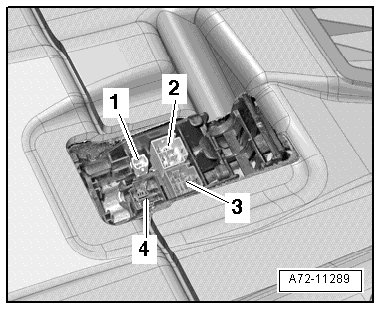
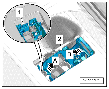
- Unclip the cover -1- in the front using the Trim Removal Wedge -3409- and remove cover in direction of -arrow- from the connector station -2-.
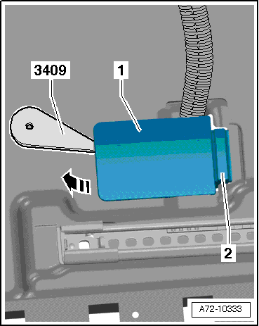
- Remove wiring bracket -3- at the top from the connector station by releasing retaining tabs.
Note
The number of connectors may vary depending on equipment. The description shows the version with the most equipment possible.
WARNING
- Follow all Safety Precautions when working with pyrotechnic components. Refer to → Chapter "Pyrotechnic Components Safety Precautions".
- Before handling pyrotechnic components (for example, disconnecting the connector), the person handling it must "discharge static electricity". This can be done by touching the door striker, for example.
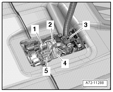
- Disconnect side airbag electrical harness connector -1- by releasing retaining tabs.
2 - Seat heating
4 - Seat adjustment voltage supply
5 - Seat Belt Latch
Airbag Adapter, Connecting
- Connect the Airbag Lockout Adapter -VAS6282- to the side airbag connector.
Caution
The Airbag Lockout Adapter -VAS6282- must stay connected to seat until seat is installed again.
Note
Ensure airbag adapter engages correctly.
Connector Station, Removing
- Open the locking mechanisms -1- with a screwdriver.
- Pull the connector station -2- upward in direction of -arrow A- and remove it in direction of -arrow B-. Lift the floor covering slightly, if necessary.
- Remove the connectors from the connector station.
Connectors, Connecting
WARNING
- Follow all Safety Precautions when working with pyrotechnic components. Refer to → Chapter "Pyrotechnic Components Safety Precautions".
- Before handling pyrotechnic components (for example, connecting the connector), the person handling it must "discharge static electricity". This can be done by touching the door striker, for example.
Connecting the electrical wiring harnesses happens in reverse order, noting the following:
Note
Make sure the connectors are installed correctly and are secure.
Connector Assignment. Refer to → Wiring diagrams, Troubleshooting & Component locations.
1 - Side Airbag
2 - Seat Heating
3 - Seat Adjustment Voltage Supply
4 - Seat Belt Latch
Note
The number of connectors may vary depending on equipment. The description shows the version with the most equipment possible.
WARNING
Ignition must be on when connecting battery. If pyrotechnic components (for example, airbag, belt tensioner) are not repaired correctly, they may deploy unintentionally after connecting battery. There must not be anyone inside the vehicle when connecting the battery.
DANGER!
When working on vehicles with the ignition already switched on or that are ready to drive there is a danger of the engine starting unexpectedly and of being poisoned by gas in enclosed areas. Risk of body parts and/or clothing being clamped or pulled.
Perform the following before switching on the ignition:
- Move the selector lever into P.
- Activate the parking brake
- Turn off the ignition.
- Open the hood
- Connect the charger, such as the Battery Charger -VAS5095A- to the jump start of the 12V vehicle electrical system.
- Turn on the ignition.
- Connect the battery GND cable with the ignition turned on. Refer to → Electrical Equipment; Rep. Gr.27; Battery; Battery, Disconnecting and Connecting.
Note
If the Airbag Indicator Lamp -K75- indicates a fault, check the Diagnostic Trouble Code (DTC) memory, erase it and check it again. Refer to Vehicle Diagnostic Tester.