Audi A6 Typ 4G: Seat Height Adjuster Handle, Removing and Installing
Special tools and workshop equipment required
- T-Handle Hook -3438-
Removing
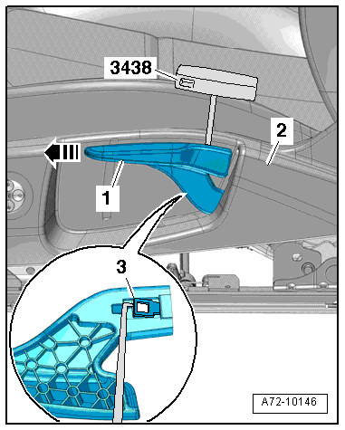
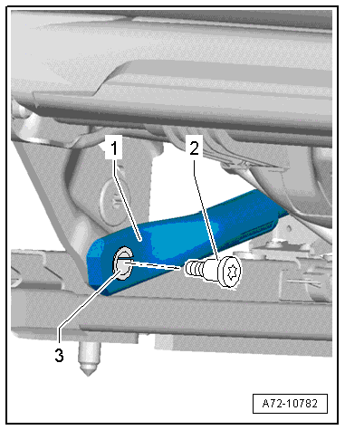
- Pull seat height adjustment handle -1- up as far as the stop and hold it in that position.
- Carefully pull the seat height adjustment handle slightly off of the front seat.
- Guide the T-Handle Hook -3438- between the seat height adjustment handle and the trim -2-.
- Release the tab -3- using the T-Handle Hook -3438- and at the same time, remove the seat height adjustment handle in the direction of -arrow- from the lever.
Installing
Install in reverse order of removal. Note the following:
Installation notes, for example tightening specifications, replacing components. Refer to → Chapter "Overview - Seat Pan, Seat Height Adjustment".
Seat Height Adjuster, Removing and Installing
Seat Height Adjuster, Removing and Installing
Removing
 Caution
Move the front seat to the highest possible position. This reduces the spring force when removing and installing the seat height adjuster.
- Move the front seat all the way forward and raise it as high as possible. Then lower it one stroke.
 WARNING
- Follow all Safety Precautions when working with pyrotechnic components. Refer to → Chapter "Pyrotechnic Components Safety Precautions".
- Before handling pyrotechnic components (for example, disconnecting the connector), the person handling it must "discharge static electricity". This can be done by touching the door striker, for example.
- Remove the front seat. Refer to → Chapter "Front Seat, Removing and Installing".
- Fasten the front seat on the Engine/Transmission Holder - Seat Repair Fixture -VAS6136-. Refer to → Chapter "Front Seat, Mounting on Fixture for Seat Repair".
- Remove the trim on the sill side. Refer to → Chapter "Seat Side Trim on Sill Panel Side, Removing and Installing, Front Seat (Manual)".
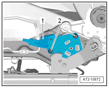
- Remove the bolts -2-.
- Remove the lever -1- from the seat height adjuster.
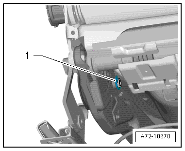
- Remove the locking washer -1- with a screwdriver.
 Note
Note
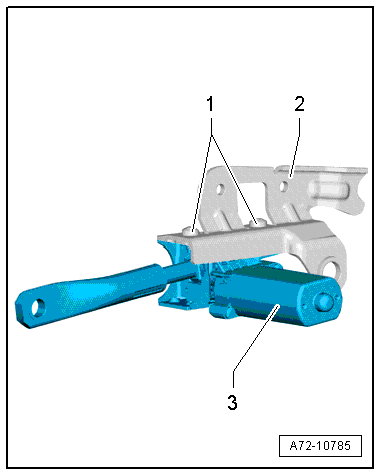
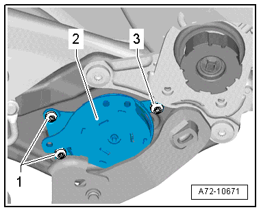
The bolts -1- and the bolt -3- are different lengths.
- Remove the bolts -1 and 3-.
- Remove the seat height adjuster -2- from the seat frame.
Installing
WARNING
- Follow all Safety Precautions when working with pyrotechnic components. Refer to → Chapter "Pyrotechnic Components Safety Precautions".
- Before handling pyrotechnic components (for example, connecting the connector), the person handling it must "discharge static electricity". This can be done by touching the door striker, for example.
Install in reverse order of removal. Note the following:
Note
Make sure the connectors are installed correctly and are secure.
WARNING
Ignition must be on when connecting battery. If pyrotechnic components (for example, airbag, belt tensioner) are not repaired correctly, they may deploy unintentionally after connecting battery. There must not be anyone inside the vehicle when connecting the battery.
DANGER!
When working on vehicles with the ignition already switched on or that are ready to drive there is a danger of the engine starting unexpectedly and of being poisoned by gas in enclosed areas. Risk of body parts and/or clothing being clamped or pulled.
Perform the following before switching on the ignition:
- Move the selector lever into P.
- Activate the parking brake
- Turn off the ignition.
- Open the hood
- Connect the charger, such as the Battery Charger -VAS5095A- to the jump start of the 12V vehicle electrical system.
- Turn on the ignition.
- Connect the battery GND cable with the ignition turned on. Refer to → Electrical Equipment; Rep. Gr.27; Battery; Battery, Disconnecting and Connecting.
Note
If the Airbag Indicator Lamp -K75- indicates a fault, check the Diagnostic Trouble Code (DTC) memory, erase it and check it again. Refer to Vehicle Diagnostic Tester.
Installation notes, for example tightening specifications, replacing components. Refer to → Chapter "Overview - Seat Pan, Seat Height Adjustment".
Seat Height Adjustment Motor, Removing and Installing
Removing
WARNING
- Follow all Safety Precautions when working with pyrotechnic components. Refer to → Chapter "Pyrotechnic Components Safety Precautions".
- Before handling pyrotechnic components (for example, disconnecting the connector), the person handling it must "discharge static electricity". This can be done by touching the door striker, for example.
- Remove the front seat. Refer to → Chapter "Front Seat, Removing and Installing".
- Fasten the front seat on the Engine/Transmission Holder - Seat Repair Fixture -VAS6136-. Refer to → Chapter "Front Seat, Mounting on Fixture for Seat Repair".
- Remove the sill-side trim:
- For the standard seat/sport seat/power sport seat. Refer to → Chapter "Seat Side Trim on Sill Panel Side, Removing and Installing, Front Seat (Power)".
- For a Multi-contour seat. Refer to → Chapter "Seat Side Trim on Sill Panel Side/Front Seat Trim, Removing and Installing, Multi-contour Seat".
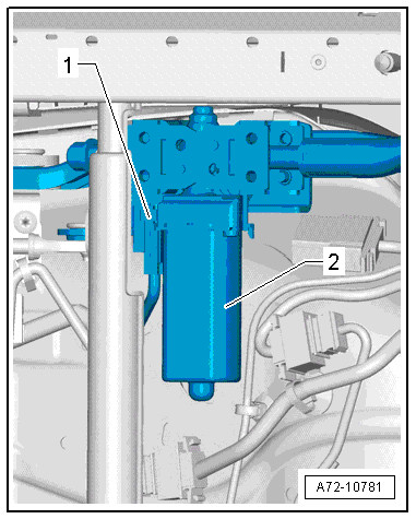
- Disconnect harness connector -1- at seat height adjustment motor -2-.
- Relieve the torsion bar tension. Refer to → Chapter "Torsion Bar, Removing and Installing".
Caution
Threaded hole in the seat pan damaged or destroyed.
When removing or installing, the adjusting spindle/seat pan bolting torque must be relieved.
Risk of damage to the bushing -3- in the bearing point (adjusting spindle/seat pan bolting).
- The bushing cannot be replaced with shop materials.
- If the bushing is damaged, the corresponding assembly parts must be replaced.
There is a risk of damaging the threads on the bolt -2-.
The bolt on the adjusting spindle has left-hand threads.
- Remove bolt -2- on the seat height adjustment motor adjusting spindle -1-.
- Remove bolt -1- for seat angle adjustment motor adjusting spindle (preset by the manufacturer).
- Move the upper seat frame as far upward as possible and support with a suitable wood block on the Engine/Transmission Holder - Seat Repair Fixture -VAS6136-.
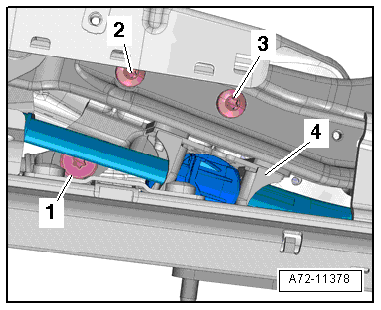
- Remove the bolts -2 and 3-.
- Remove fixture with height adjustment motor -4- from the seat pan.
- Remove the bolts -1-.
- Remove bracket -2- from the seat height adjustment motor -3-.
Installing
Install in reverse order of removal. Note the following:
WARNING
- Follow all Safety Precautions when working with pyrotechnic components. Refer to → Chapter "Pyrotechnic Components Safety Precautions".
- Before handling pyrotechnic components (for example, connecting the connector), the person handling it must "discharge static electricity". This can be done by touching the door striker, for example.
- Observe all measures when installing the front seat. Refer to → Chapter "Front Seat, Removing and Installing".
Installation notes, for example tightening specifications, replacing components. Refer to → Chapter "Overview - Seat Pan, Seat Height Adjustment".