Audi A6 Typ 4G: Front Seat Wire Routing
 Note
Note
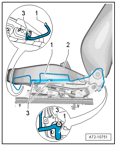
The wires between the seat pan and the connector station are inside a double-shell corrugated tube in the so-called modulate wiring routing.
Special tools and workshop equipment required
- Trim Removal Wedge -3409-
Opening the Corrugated Tube and Removing the Individual Wire
 WARNING
- Follow all Safety Precautions when working with pyrotechnic components. Refer to → Chapter "Pyrotechnic Components Safety Precautions".
- Before handling pyrotechnic components (for example, disconnecting the connector), the person handling it must "discharge static electricity". This can be done by touching the door striker, for example.
- Remove the front seat. Refer to → Chapter "Front Seat, Removing and Installing".
- Fasten the front seat on the Engine/Transmission Holder - Seat Repair Fixture -VAS6136-. Refer to → Chapter "Front Seat, Mounting on Fixture for Seat Repair".
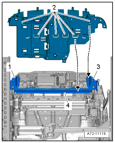
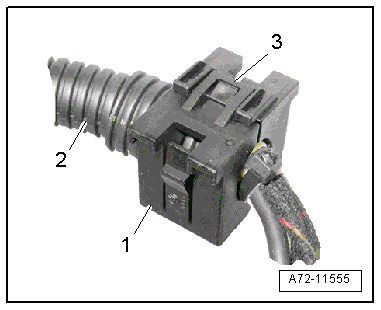
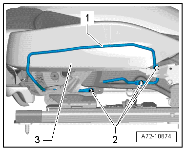
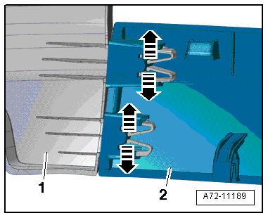
- Release the retainer -3- and open the front cable holder -1- using the Trim Removal Wedge -3409-.
- Remove wiring bracket from the corrugated tube -2-.
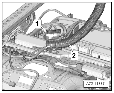
- Open rear wiring bracket -1- for modular wire routing on the seat pan lower frame using a screwdriver and remove corrugated tube -2-.
Note
For replacing a faulty wire or opening the corrugated tube for the side airbag. Refer to → Electrical Equipment General Information; Rep. Gr.97; Wiring Harness and Connector Repairs or → Chapter "Front Side Airbag with Igniter, Removing and Installing".
Installing Individual Wires and Closing the Corrugated Tube
Install in reverse order of removal. Note the following:
- When bundling and placing individual wires in the corrugated tube, make sure the wires are not twisted.
- Insert the corrugated tube -2- in the wiring bracket -1- in such a way that it terminates flush with the wiring bracket.
Note
- When installing, position all cable ties, wire holders and retaining clips in same place.
- Make sure the connectors are installed correctly and are secure.
WARNING
- Follow all Safety Precautions when working with pyrotechnic components. Refer to → Chapter "Pyrotechnic Components Safety Precautions".
- Before handling pyrotechnic components (for example, connecting the connector), the person handling it must "discharge static electricity". This can be done by touching the door striker, for example.
- Observe all measures when installing the front seat. Refer to → Chapter "Front Seat, Removing and Installing".
Installation notes, for example tightening specifications, replacing components. Refer to → Chapter "Overview - Seat Pan, Modular Wiring Routing".
Seat Rail Cover, Removing and Installing
Special tools and workshop equipment required
- Trim Removal Wedge -3409-
Note
- Proceed very carefully when removing and installing because it is relatively easy to damage the cover.
- For reasons of clarity, the surrounding area is not shown.
Removing
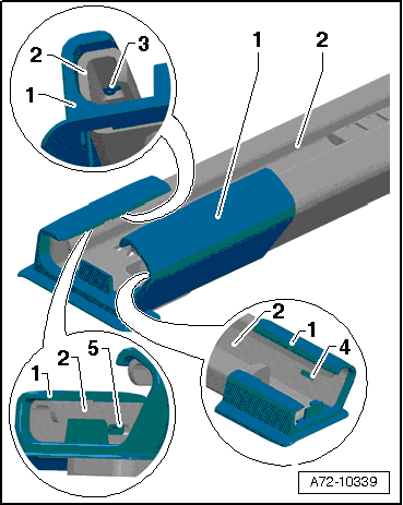
- Pry the spindle cover off of the seat rail cover and the seat rail bolt using the Trim Removal Wedge -3409-arrows.
- Open the tabs -3, 4 and 5- on the seat rail carefully with a screwdriver and remove the cover -1- from the seat rail -2-.
Installing
Install in reverse order of removal. Note the following:
Installation notes, for example tightening specifications, replacing components. Refer to → Chapter "Overview - Front Seat".
Seat Side Trim on Sill Panel Side, Removing and Installing, Front Seat (Manual)
Special tools and workshop equipment required
- Assembly Tool -3399-
Removing
- Move the front seat all the way forward/up.
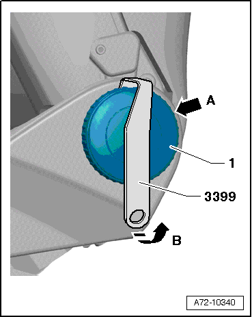
- Turn the backrest adjustment wheel -1- until one catch is visible from behind -arrow A-. Use a flashlight if necessary.
- Attach the Assembly Tool -3399- to the catch and pry off the hand wheel -arrow B-.
- Turn the backrest adjustment wheel 120º further and repeat the process.
- Remove the backrest adjustment hand wheel.
- Remove the seat height adjustment handle. Refer to → Chapter "Seat Height Adjuster Handle, Removing and Installing".
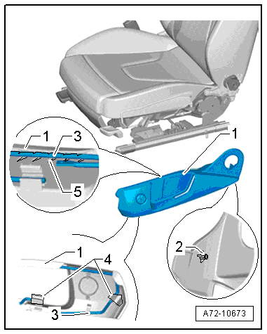
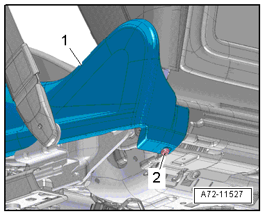
- Remove the expanding rivet -2- from the sill-side trim -1-.
- Carefully remove the trim from the front seat, open the clips -4- on the trim and unclip the bracket -3-
- Disengage the sill-side rear trim -1- from the backrest hinge and lower seat frame.
- Pull the sill-side trim slightly forward off the bracket and remove it upward.
Note
Be careful not to damage the mounts -5- and the tab -2- when removing the trim.
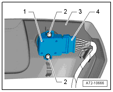
- Vehicles with four-way lumbar support: Disconnect the connector -4- on the lumbar support adjustment switch -1-.
- Remove the sill-side trim -3-.
Note
Ignore item -2-.
Seat Side Trim Bracket, Removing
- Remove the bolts -2-.
- Remove the bracket -1- from the front seat -3-. Loosen the cable tie off the bracket if necessary.
Installing
Install in reverse order of removal. Note the following:
Note
- Make sure the tab -2- is seated correctly.
- Make sure the sill side trim -1- is engaged correctly on the retaining bracket -3- and the locking clips -4- are closed.
- Make sure the connectors are installed correctly and are secure.
Information for installation: for example, tightening specifications, replacing body parts. Refer to → Chapter "Overview - Seat Pan, Sill Panel/Tunnel Side Seat Side Trim" and → Chapter "Overview - Seat Pan, Seat Side Trim Bracket on Sill Panel Side".
Seat Side Trim on Sill Panel Side, Removing and Installing, Front Seat (Power)
Removing
- Move the front seat all the way forward/up.
- Remove the expanding rivet -2- from the sill-side trim -1-.
- Open the clip -3- on the trim.
- Disengage the sill-side rear trim -1- from the backrest hinge and lower seat frame.
- Pull the trim slightly off the front seat and unclip the trim on the sill-side from the bracket -2-.
Note
Be careful not to damage the bracket -4- when removing the trim.
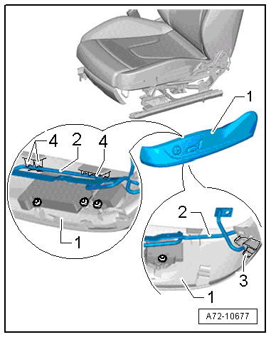
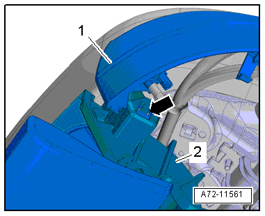
- Release the catch -arrow- on the storage compartment -2- and remove the sill-side trim -1- upward.
- Pull the sill-side trim slightly forward off the bracket and remove it upward.
- Disconnect the connectors:
1 - Driver Seat Adjustment Control Head -E470-/Front Passenger Seat Adjustment Control Head -E471-
2 - D river Seat Lumbar Support Adjustment Switch -E176-/Front Passenger Seat Lumbar Support Adjustment Switch -E177-
- Free up electrical wire on the bracket -3-.
- Remove sill side trim.
Seat Side Trim Bracket, Removing
- Remove the bolts -3-.
- Remove the bracket -1- from the front seat -2-. Loosen the cable tie off the bracket if necessary.
Installing
Install in reverse order of removal. Note the following:
Note
- Make sure the connectors are installed correctly and are secure.
- Route the connectors and wires as illustrated.
- Make sure the trim on the sill side is correctly attached to the mounting bracket.
Information for installation: for example, tightening specifications, replacing body parts. Refer to → Chapter "Overview - Seat Pan, Sill Panel/Tunnel Side Seat Side Trim" and → Chapter "Overview - Seat Pan, Seat Side Trim Bracket on Sill Panel Side".
Seat Side Trim on Sill Panel Side/Front Seat Trim, Removing and Installing, Multi-contour Seat
Removing
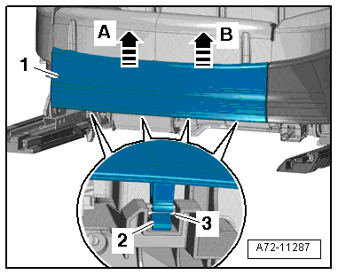
- Move the front seat all the way to the rear and then into its highest position.
- Move the seat depth adjuster to the rear.
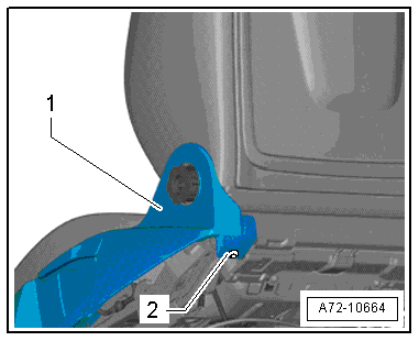
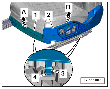
- Release lower retaining tabs -2- on the holder -3- and pull front trim -1- upward -A and B arrows-.
- Move the front seat all the way forward/up.
- Remove the front belt end fitting. Refer to → Chapter "Front Belt End Fitting, Removing and Installing".
- Pull sill side trim -1- upward and detach at the holder -A, B and C arrows- by releasing the lower retaining tabs -2- on the holder -3-.
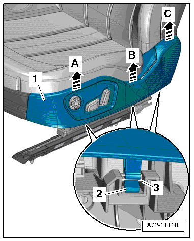
- Pull off sill side trim -2- together with front trim -1--A and B arrows- and remove.
Note
In order to prevent damage, make sure that all retaining tabs -4- on the holder -3- are correctly released.
- Disconnect the connectors:
1 - Driver Seat Switch Module -E663-/Front Passenger Seat Switch Module -E664-
2 - Driver Side Massage Function Button -E670-/Front Passenger Massage Function Button -E671-
3 - Driver Seat Switch Module 2 -E667-/Front Passenger Seat Switch Module 2 -E668-
- Free up the wire from the bracket -4-.
- Remove sill side trim.
- Disconnect sill side trim -1- from the front trim -2- by releasing retaining tabs -arrows-.
Seat Side Trim Bracket, Removing
- Disengage the sill-side seat cover molding on the lower seat frame. Refer to → Chapter "Seat Pan Cover and Cushion, Removing and Installing, Multi-contour Seat".
- Remove the bolts -2- and remove the bracket -1-.
Installing
Install in reverse order of removal. Note the following:
Note
- Make sure the connectors are installed correctly and are secure.
- Route the connectors and wires as illustrated.
Installation notes, for example tightening specifications, replacing components. Refer to → Chapter "Overview - Seat Pan, Sill Panel/Tunnel Side Seat Side Trim".
Front Seat Trim Bracket/Compressor/Control Module, Removing and Installing, Multi-contour Seat
Removing
WARNING
- Follow all Safety Precautions when working with pyrotechnic components. Refer to → Chapter "Pyrotechnic Components Safety Precautions".
- Before handling pyrotechnic components (for example, disconnecting the connector), the person handling it must "discharge static electricity". This can be done by touching the door striker, for example.
- Remove the front seat. Refer to → Chapter "Front Seat, Removing and Installing".
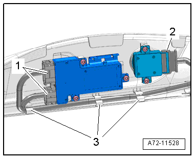
Multi-contour Seat through 08/2012:
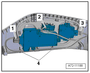
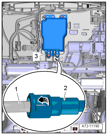
- Disconnect the connector -3-.
- Carefully release the retainer -arrow- and remove the pneumatic line -1- from the compressor -2-.
- Free up pneumatic line to the compressor.
- Remove memory seat/steering column adjustment control module. Refer to → Chapter "Seat/Steering Column Adjustment Control Module with Memory Function, Removing and Installing".
- Remove sill side trim together with front trim. Refer to → Chapter "Seat Side Trim on Sill Panel Side/Front Seat Trim, Removing and Installing, Multi-contour Seat".
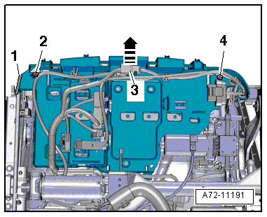
- Disengage the tunnel side seat cover molding -1- from the bracket. Refer to → Chapter "Seat Pan Cover and Cushion, Removing and Installing, Multi-contour Seat".
- Free up the electric wire -3- from the bracket.
- Remove the bolts -2- and -4- and the bracket -arrow-.
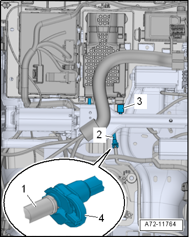
Multi-contour Seat from 09/2012:
- Disconnect the connector -2-.
- Disconnect the pneumatic line -1- from the compressor.
- Remove memory seat/steering column adjustment control module. Refer to → Chapter "Seat/Steering Column Adjustment Control Module with Memory Function, Removing and Installing".
- Remove sill side trim together with front trim. Refer to → Chapter "Seat Side Trim on Sill Panel Side/Front Seat Trim, Removing and Installing, Multi-contour Seat".
- Disengage the tunnel side seat cover molding -1- from the bracket. Refer to → Chapter "Seat Pan Cover and Cushion, Removing and Installing, Multi-contour Seat".
- Free up the electric wire -3- from the bracket.
- Remove the bolts -2 and 4- and the bracket -arrow-.
Installing
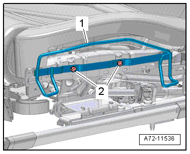
- Insert the bracket for the front trim -arrows-. When doing this make sure the tabs -2- fit into the bracket -1, 3 and 4-.
Installation is performed in reverse order of removal, noting the following:
WARNING
- Follow all Safety Precautions when working with pyrotechnic components. Refer to → Chapter "Pyrotechnic Components Safety Precautions".
- Before handling pyrotechnic components (for example, connecting the connector), the person handling it must "discharge static electricity". This can be done by touching the door striker, for example.
- Observe all measures when installing the front seat. Refer to → Chapter "Front Seat, Removing and Installing".
Installation notes, for example tightening specifications, replacing components. Refer to → Chapter "Overview - Seat Pan, Sill Panel/Tunnel Side Seat Side Trim".