Audi A6 Typ 4G: Seat Forward/Back Adjustment, Servicing
 Note
Note
To repair the seat forward/back adjustment, there is a repair kit available. Refer to the Parts Catalog.
Procedure
- Front seat is removed (refer to → Chapter "Front Seat, Removing and Installing") and placed on a soft surface.
- Move the seat height- and angle adjuster into its highest position.
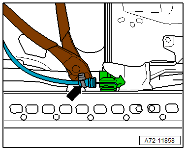
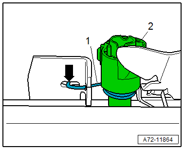
- Cut the cable tie -arrow- on the release cable bracket.
- Disengage the release cable at the bracket and the release lever for the seat forward/back adjustment.
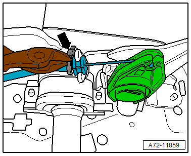
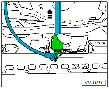
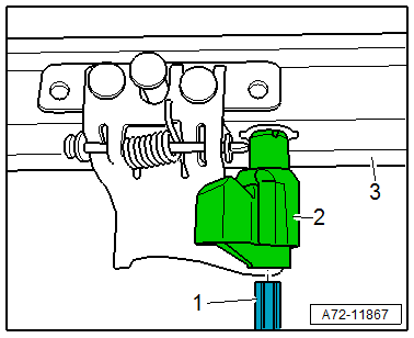
- Cut the cable tie -arrow- on the release cable bracket.
- Disengage the release cable at the bracket and at the release cable retainer for the seat forward/back adjustment.
 Caution
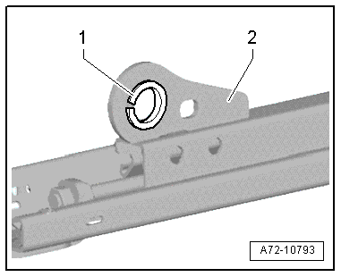
Risk of damaging the bushings -1- in the bearing points -2- (upper/lower frame bolted connection).
- The bushings cannot be replaced with workshop materials.
- If the bushings are damaged, the corresponding assembly parts must be replaced.
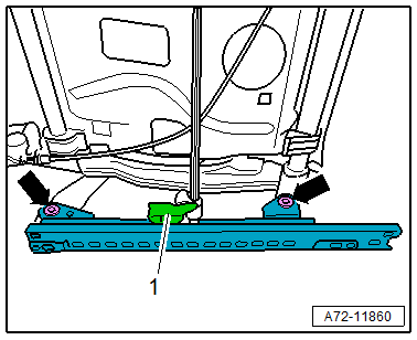
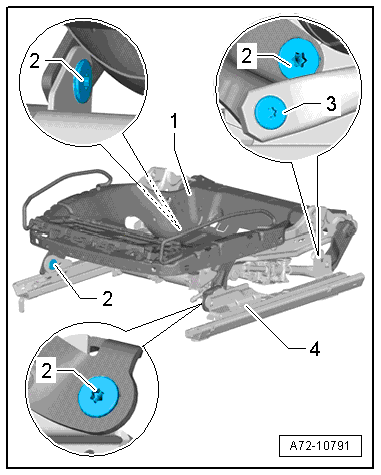
- Remove the bolts -arrows- on the inside of the seat (transmission tunnel side).
- Remove the seat rail by slightly lifting the release lever -1- for the lock pin.
- Remove the connecting rod -2- from the release lever -1- on the outside of the seat (sill-side) -arrow-.
- Remove the release lever with the spring.
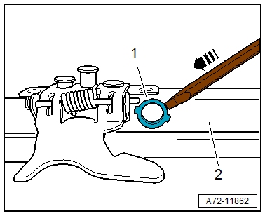
- Pry out the bushing -1- on both seat rails -2- in direction of -arrow-.
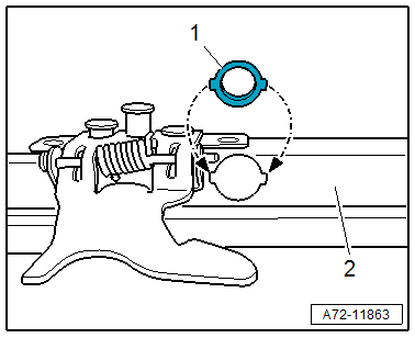
- Insert the new bushings -1- in both seat rails -2- and press firmly.
- The tabs on the bushings point to the openings in the seat rails.
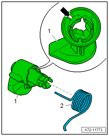
- Insert the spring -2- into the release lever -1- for the outer seat side (sill-side).
- The straight arm of the spring must engage in the hole -arrow- on the release lever.
- Insert the release lever -2- for the outer seat side (sill-side) into the bushing in the seat rail.
- The spring -1- must engage in the opening -arrow- on the outer seat rail.
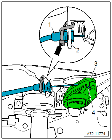
- Guide the seat forward/back adjuster release cable -2- around the release lever -3- and engage the release cable nipple into the release lever -arrow A-.
- Engage the release cable sheath -1- in the bracket -arrow B-.
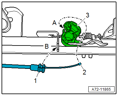
- Secure the release cable sheath -1- with a cable tie -arrow- in the bracket -2-.
- The cable tie must be looped in a figure "8" around the release cable sheath and the bracket as shown.
- Insert the connecting rod -4- into the release lever -3- on the outer seat rail until it stops.
- The connecting rod only fits in one position.
- If the connecting rod cannot be inserted easily, deburr the ends of the connecting rod.
- Insert the release lever -2- for the inner seat rail (tunnel side) into the seat rail -3-.
- Install the seat rail together with the release lever on the connecting rod -1-.
- The connecting rod only fits in one position.
- If the connecting rod cannot be inserted easily, deburr the ends of the connecting rod.
- Tighten the bolts -arrows- on the inside of the seat (transmission tunnel side) (22 Nm).
Note
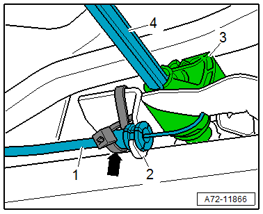
Underneath the connecting rod, the seat forward/back adjuster release cable is guided forward to the lever for seat forward/back adjustment.
- Engage the nipple -4- at the release cable retainer for the seat forward/back adjustment -3-.
- Engage the release cable sheath -1- into the bracket -2-.
- Secure the release cable sheath with a cable tie -arrow- in the bracket.
- The cable tie must be looped in a figure "8" around the release cable sheath and the bracket as shown.
- Install the front seat. Refer to → Chapter "Front Seat, Removing and Installing".
Assembly is performed in reverse order.
Lower Seat Frame/Forward/Back Adjustment Motor, Removing and Installing
Removing
 WARNING
- Follow all Safety Precautions when working with pyrotechnic components. Refer to → Chapter "Pyrotechnic Components Safety Precautions".
- Before handling pyrotechnic components (for example, disconnecting the connector), the person handling it must "discharge static electricity". This can be done by touching the door striker, for example.
- Move front seat to the highest position possible to keep the torsion bar tension as low as possible.
- Remove the front seat. Refer to → Chapter "Front Seat, Removing and Installing".
- Remove the seat position sensor on the lower seat frame. Refer to → Chapter "Seat Position Sensor, Removing and Installing".
- Remove the front seat belt latch. Refer to → Chapter "Front Seat Belt Latch, Removing and Installing".
- Unclip the wire from the lower seat frame and set aside.
- Disconnect the connector on the seat forward/back adjustment motor.
- Unclip modular wire routing bracket on the seat pan lower frame.
Standard Seat/Sport Seat/Super Sport Seat
Caution
Danger of damaging the threaded holes or the bushing in the bearing points (connecting the upper/lower frame).
A second technician must be pushing down on the seat backrest when removing the following bolts.
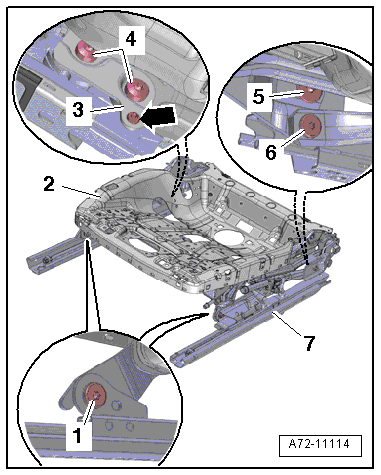
There is a risk of damaging the threads on the bolt -3-.
The bolt on the adjusting spindle has left-hand threads.
- Remove the bolt -3-.
- Remove the bolts -2-.
- Remove the upper frame -1- from the lower frame -4-.
Multi-Contour Seat
Caution
Danger of damaging the threaded holes or the bushing in the bearing points (connecting the upper/lower frame).
A second technician must be pushing down on the seat backrest when removing the following bolts.
There is a risk of damaging the threads on the bolt -6-.
The bolt on the adjusting spindle has left-hand threads.
- Remove the bolt -6-.
- Remove the bolts -4-.
- Detach the retaining plate -3- on the seat pan lower frame -arrow- and remove.
- Remove the bolts -1 and 5-.
- Remove upper frame -2- from the lower frame -7-.
Procedure for All Seat Versions
Caution
Risk of damaging the bushings -1- in the bearing points -2- (upper/lower frame bolted connection).
- The bushings cannot be replaced with workshop materials.
- If the bushings are damaged, the corresponding assembly parts must be replaced.
Installing
WARNING
- Follow all Safety Precautions when working with pyrotechnic components. Refer to → Chapter "Pyrotechnic Components Safety Precautions".
- Before handling pyrotechnic components (for example, connecting the connector), the person handling it must "discharge static electricity". This can be done by touching the door striker, for example.
- Observe all measures when installing the front seat. Refer to → Chapter "Front Seat, Removing and Installing".
Install in reverse order of removal. Note the following:
Installation instructions: tightening specifications, replacing body parts. Refer to → Chapter "Overview - Seat Pan, Seat Forward/Back Adjustment", → Chapter "Overview - Seat Pan, Safety Ground Lock", and → Chapter "Overview - Seat Pan, Seat Height Adjustment".
Seat Frame, Replacing, Front Seat (Manual)
Note
There is no separation between the upper and lower (lower seat frame) on the manual standard front seat/Sport front seat.
Removing
WARNING
- Follow all Safety Precautions when working with pyrotechnic components. Refer to → Chapter "Pyrotechnic Components Safety Precautions".
- Before handling pyrotechnic components (for example, disconnecting the connector), the person handling it must "discharge static electricity". This can be done by touching the door striker, for example.
Caution
Move the front seat to the highest possible position. This reduces the spring force when removing and installing the seat height adjuster.
- Move the front seat all the way forward and raise it as high as possible. Then lower it one stroke.
- Remove the front seat. Refer to → Chapter "Front Seat, Removing and Installing".
- Remove the backrest. Refer to → Chapter "Front Backrest, Removing and Installing, Standard Seat/Sport Seat/Super Sport Seat".
- Remove seat cover with seat cushion. Refer to → Chapter "Lower Seat Frame Cover and Cushion, Removing and Installing, Standard Seat".
Note
Remove the wires and components and install them into the new seat frame.
- Remove the front seat belt latch. Refer to → Chapter "Front Seat Belt Latch, Removing and Installing".
- Remove the storage compartment. Refer to → Chapter "Storage Compartment, Removing and Installing".
- Remove the seat height adjuster. Refer to → Chapter "Seat Height Adjuster, Removing and Installing".
- Remove wiring harnesses and individual wires from the seat frame.
Installing
WARNING
- Follow all Safety Precautions when working with pyrotechnic components. Refer to → Chapter "Pyrotechnic Components Safety Precautions".
- Before handling pyrotechnic components (for example, connecting the connector), the person handling it must "discharge static electricity". This can be done by touching the door striker, for example.
- Observe all measures when installing the front seat. Refer to → Chapter "Front Seat, Removing and Installing".
Install in reverse order of removal. Note the following:
- Install all the components and wires into the new seat frame.
Information for installation: for example, tightening specifications, replacing body parts. Refer to → Chapter "Overview - Front Seat, Standard Seat/Sport Seat" and → Chapter "Overview - Seat Pan, Seat Forward/Back Adjustment".
