Audi A6 Typ 4G: Upper Seat Frame, Removing and Installing
 Note
Note
The following describes removing and installing a lower seat frame without a seat depth adjuster. Removing and installing a lower seat frame with a seat depth adjuster is identical.
Removing
 WARNING
- Follow all Safety Precautions when working with pyrotechnic components. Refer to → Chapter "Pyrotechnic Components Safety Precautions".
- Before handling pyrotechnic components (for example, disconnecting the connector), the person handling it must "discharge static electricity". This can be done by touching the door striker, for example.
 Caution
Move the front seat to the highest possible position. This reduces the spring force when removing and installing the torsion bar and the risk of damaging the threaded connections between upper/lower frames of the seat pan.
- Remove the front seat. Refer to → Chapter "Front Seat, Removing and Installing".
- Remove the backrest. Refer to → Chapter "Front Backrest, Removing and Installing".
- Remove seat cover with seat cushion. Refer to → Chapter "Seat Pan Cover and Cushion, Removing and Installing".
- Disconnect the connector on the seat forward/back adjustment motor.
- Unclip modular wire routing bracket on the seat pan lower frame.
- Remove seat position sensor from the lower frame. Refer to → Chapter "Seat Position Sensor, Removing and Installing".
- Disconnect the connector from the front seat belt latch.
- Unclip the wire from the lower seat frame and set aside.
Standard Seat/Sport Seat/Super Sport Seat
Caution
Danger of damaging the threaded holes or the bushing in the bearing points (connecting upper/lower frame).
A second technician must be pushing down on the seat backrest when removing the following bolts.
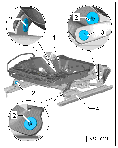
There is a risk of damaging the threads on the bolt -3-.
The bolt on the adjusting spindle has left-hand threads.
- Remove the bolt -3-.
- Remove the bolts -2- and then remove the upper frame -1- from the lower frame -4-.
Multi-Contour Seat
Caution
Danger of damaging the threaded holes or the bushing in the bearing points (connecting upper/lower frame).
A second technician must be pushing down on the seat backrest when removing the following bolts.
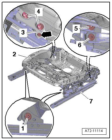
There is a risk of damaging the threads on the bolt -6-.
The bolt on the adjusting spindle has left-hand threads.
- Remove the bolt -6-.
- Remove the bolts -4-.
- Detach the retaining plate -3- on the seat pan lower frame -arrow- and remove.
- Remove the bolts -1 and 5- and remove the upper frame -2- from the lower frame -7-.
- Remove the front seat belt latch. Refer to → Chapter "Front Seat Belt Latch, Removing and Installing".
Procedure for All Seat Versions
Caution
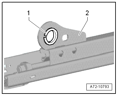
Risk of damaging the bushings -1- in the bearing points -2- (upper/lower frame bolted connection).
- The bushings cannot be replaced with workshop materials.
- If the bushings are damaged, the corresponding assembly parts must be replaced.
- Remove the bracket with the Memory Seat/Steering Column Adjustment Control Module -J136-/Front Passenger Memory Seat Control Module -J521-. Refer to → Chapter "Front Seat Control Module Bracket, Removing and Installing".
- Vehicles with seat depth adjuster: remove the seat depth adjuster. Refer to → Chapter "Seat Depth Adjuster, Removing and Installing, Multi-contour Seat".
- Vehicles with seat ventilation: remove the fan for the seat cushion. Refer to → Chapter "Seat Cushion Blower Fan, Removing and Installing, Standard Seat/Sport Seat/Super Sport Seat".
- Remove the Driver Seat Height Adjustment Motor -V245-/Front Passenger Seat Height Adjustment Motor -V246-. Refer to → Chapter "Seat Height Adjustment Motor, Removing and Installing".
- Remove the Driver Seat Angle Adjustment Motor -V243-/Front Passenger Seat Angle Adjustment Motor -V244-. Refer to → Chapter "Seat Angle Adjustment Motor, Removing and Installing".
- Remove wiring harnesses and individual wires from seat pan upper frame.
Installing
WARNING
- Follow all Safety Precautions when working with pyrotechnic components. Refer to → Chapter "Pyrotechnic Components Safety Precautions".
- Before handling pyrotechnic components (for example, connecting the connector), the person handling it must "discharge static electricity". This can be done by touching the door striker, for example.
- Observe all measures when installing the front seat. Refer to → Chapter "Front Seat, Removing and Installing".
Install in reverse order of removal. Note the following:
Installation instructions: tightening specifications, replacing body parts. Refer to → Chapter "Overview - Seat Pan, Seat Forward/Back Adjustment", → Chapter "Overview - Seat Pan, Safety Ground Lock", and → Chapter "Overview - Seat Pan, Seat Height Adjustment".
Torsion Bar, Removing and Installing
Special tools and workshop equipment required
- Engine Sling - Engine Bracket -2024A/1-
- Driveshaft Handle -3145-
- M10 x 30 bolt and nut
Removing
WARNING
- Follow all Safety Precautions when working with pyrotechnic components. Refer to → Chapter "Pyrotechnic Components Safety Precautions".
- Before handling pyrotechnic components (for example, disconnecting the connector), the person handling it must "discharge static electricity". This can be done by touching the door striker, for example.
Caution
Move the front seat to the highest possible position. This reduces the spring force when removing and installing the torsion bar and the risk of damaging the threaded connections between upper/lower frames of the seat pan.
- Remove the front seat. Refer to → Chapter "Front Seat, Removing and Installing".
- Fasten the front seat on the Engine/Transmission Holder - Seat Repair Fixture -VAS6136-. Refer to → Chapter "Front Seat, Mounting on Fixture for Seat Repair".
- Remove the backrest. Refer to → Chapter "Front Backrest, Removing and Installing".
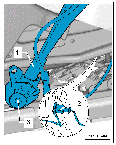
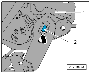
- Loosen the threaded connection -3- on the front seat belt latch -1-.
- Move the front seat belt latch downward.
Note
Ignore -item 2-.
WARNING
The torsion bar exhibits considerable spring force. Always follow the points below to avoid accidents:
- Always remove and install the torsion bar in the sequence described and only using the tools specified.
- Never use pliers and other levers.
- Do not stand directly in front of the torsion bar when removing and installing it. Stand off to the side.
- Prevent the Engine Sling - Engine Bracket -2024A/1- using the M10x30 bolt -3- and nut from spreading.
- Position the Driveshaft Handle -3145- with the Engine Sling - Engine Bracket -2024A/1- on the torsion bar -1-.
2 - Seat pan
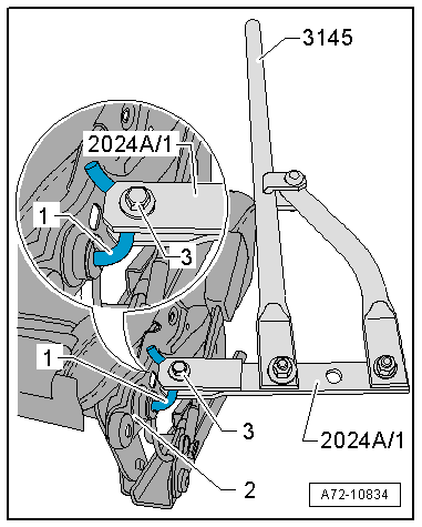
- Carefully turn torsion bar -1- until it can be detached using a screwdriver from the slot -arrow- of the seat pan.
- Relieve the tension of the torsion bar and remove it from the seat pan -2-.
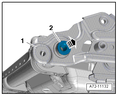
Mounts for the torsion bar
- Pry out bearing -2- from the guide on the seat pan using a flat-head screwdriver -1- in direction of -arrow-.
Installing
WARNING
The torsion bar exhibits considerable spring force. Always follow the points below to avoid accidents:
- Always remove and install the torsion bar in the sequence described and only using the tools specified.
- Never use pliers and other levers.
- Do not stand directly in front of the torsion bar when removing and installing it. Stand off to the side.
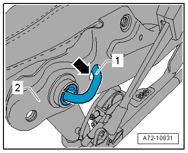
- Slide the torsion bar -1- into the mount until the end -arrow- comes into contact with the seat pan -2-.
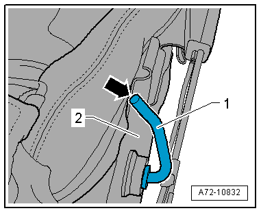
- Make sure that the torsion bar -2- correctly sits in the bracket -arrow- of the seat pan -1-.
- Prevent the Engine Sling - Engine Bracket -2024A/1- using the M10x30 bolt -3- and nut from spreading.
- Position the Driveshaft Handle -3145- with the Engine Sling - Engine Bracket -2024A/1- on the torsion bar -1-.
- Carefully turn torsion bar -1- until it can be hooded in the slot -arrow- of the seat pan.
Installation is performed in reverse order of removal, while noting the following:
WARNING
- Follow all Safety Precautions when working with pyrotechnic components. Refer to → Chapter "Pyrotechnic Components Safety Precautions".
- Before handling pyrotechnic components (for example, connecting the connector), the person handling it must "discharge static electricity". This can be done by touching the door striker, for example.
- Observe all measures when installing the front seat. Refer to → Chapter "Front Seat, Removing and Installing".
Installation notes, for example tightening specifications, replacing components. Refer to → Chapter "Overview - Seat Pan, Torsion Bar".
