Audi A6 Typ 4G: Seat Side Trim on the Tunnel Side, Removing and Installing
Removing
 WARNING
- Follow all Safety Precautions when working with pyrotechnic components. Refer to → Chapter "Pyrotechnic Components Safety Precautions".
- Before handling pyrotechnic components (for example, disconnecting the connector), the person handling it must "discharge static electricity". This can be done by touching the door striker, for example.
- Remove the front seat. Refer to → Chapter "Front Seat, Removing and Installing".
- Fasten the front seat on the Engine/Transmission Holder - Seat Repair Fixture -VAS6136-. Refer to → Chapter "Front Seat, Mounting on Fixture for Seat Repair".
Standard Seat/Sport Seat/Super Sport Seat
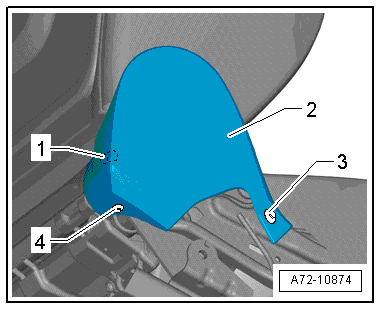
- Remove the expanding rivets -3 and 4-.
- Disengage the tunnel-side trim -2- from the backrest hinge and remove it.
 Note
Note
Make sure the tab -1- is not damaged when removing the trim.
Multi-Contour Seat
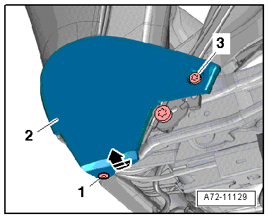
- Remove the expanding rivet -1-.
- Remove the bolt -3-.
- Detach tunnel side trim -2- on the backrest hinge trim -arrow- and remove.
Installing
WARNING
- Follow all Safety Precautions when working with pyrotechnic components. Refer to → Chapter "Pyrotechnic Components Safety Precautions".
- Before handling pyrotechnic components (for example, connecting the connector), the person handling it must "discharge static electricity". This can be done by touching the door striker, for example.
- Observe all measures when installing the front seat. Refer to → Chapter "Front Seat, Removing and Installing".
Install in reverse order of removal. Note the following:
Note
- Make sure the tab -1- is seated correctly.
- Make sure the connectors are installed correctly and are secure.
Installation notes, for example tightening specifications, replacing components. Refer to → Chapter "Overview - Seat Pan, Sill Panel/Tunnel Side Seat Side Trim".
Seat Forward/Back Adjustment Handle, Removing and Installing
Removing
- Push the headrest into the lowest position.
- Move the front seat all the way to the rear and then into its highest position.
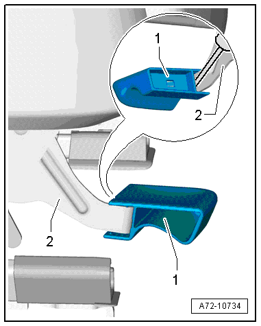
- Pry the handle -2- off the seat forward/back adjustment -1- by using a screwdriver to press down the clip locking spring.
Note
If it is not possible to remove the handle as described, then remove the storage compartment. Refer to → Chapter "Front Center Console Storage Compartment, Removing and Installing".
Installing
Install in reverse order of removal. Note the following:
Installation notes, for example tightening specifications, replacing components. Refer to → Chapter "Overview - Seat Pan, Seat Forward/Back Adjustment".
Seat Forward/Back Adjustment Release Cable, Removing and Installing
Removing
WARNING
- Follow all Safety Precautions when working with pyrotechnic components. Refer to → Chapter "Pyrotechnic Components Safety Precautions".
- Before handling pyrotechnic components (for example, disconnecting the connector), the person handling it must "discharge static electricity". This can be done by touching the door striker, for example.
- Remove the front seat. Refer to → Chapter "Front Seat, Removing and Installing".
- Fasten the front seat on the Engine/Transmission Holder - Seat Repair Fixture -VAS6136-. Refer to → Chapter "Front Seat, Mounting on Fixture for Seat Repair".
- Open the cable tie or unclip the clip on the lower seat frame.
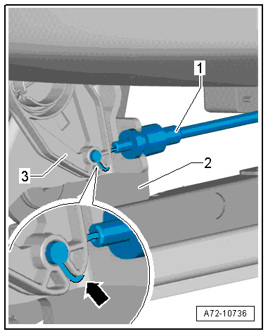
- Disengage the release cable bracket -1- from the seat forward/back adjustment -2-.
- Disengage the end of the release cable -arrow- at release cable retainer lever -3- of the seat forward/back adjuster.
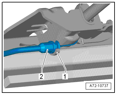
- Disengage the release cable bracket -2- from the seat forward/back adjustment -1-.
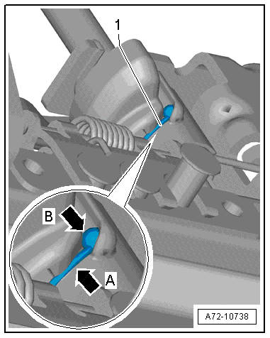
- Disengage the release cable -1- that seat forward/back release cable mount -arrow A-.
- Disengage the ball-shaped end of the release cable -arrow B- at the seat forward/back adjuster groove.
- Remove the release cable.
Installing
WARNING
- Follow all Safety Precautions when working with pyrotechnic components. Refer to → Chapter "Pyrotechnic Components Safety Precautions".
- Before handling pyrotechnic components (for example, connecting the connector), the person handling it must "discharge static electricity". This can be done by touching the door striker, for example.
Install in reverse order of removal. Note the following:
Note
Make sure the connectors are installed correctly and are secure.
WARNING
Ignition must be on when connecting battery. If pyrotechnic components (for example, airbag, belt tensioner) are not repaired correctly, they may deploy unintentionally after connecting battery. There must not be anyone inside the vehicle when connecting the battery.
DANGER!
When working on vehicles with the ignition already switched on or that are ready to drive there is a danger of the engine starting unexpectedly and of being poisoned by gas in enclosed areas. Risk of body parts and/or clothing being clamped or pulled.
Perform the following before switching on the ignition:
- Move the selector lever into P.
- Activate the parking brake
- Turn off the ignition.
- Open the hood
- Connect the charger, such as the Battery Charger -VAS5095A- to the jump start of the 12V vehicle electrical system.
- Turn on the ignition.
- Connect the battery Ground (GND) cable with the ignition turned on. Refer to → Electrical Equipment; Rep. Gr.27; Battery; Battery, Disconnecting and Connecting.
Note
If the Airbag Indicator Lamp -K75- indicates a fault, check the Diagnostic Trouble Code (DTC) memory, erase it and check it again. Refer to Vehicle Diagnostic Tester.
Installation notes, for example tightening specifications, replacing components. Refer to → Chapter "Overview - Seat Pan, Seat Forward/Back Adjustment".
Release Cable Retainer/Seat Forward/Back Adjustment Lever and Spring, Removing and Installing
Removing
- Push the headrest into the lowest position.
- Move the front seat all the way to the rear and then into its highest position.
- Disengage the release cable bracket -1- from the seat forward/back adjustment -2-.
- Disengage the end of the release cable -arrow- at release cable retainer lever -3- of the seat forward/back adjuster.
- Turn the release cable retainer lever forward and remove it.
- Remove the spring if necessary.
Installing
Installation is performed in reverse order of removal, noting the following:
Note
The release cable retainer lever is the same for the driver and front passenger seat. The spring is different for the driver and front passenger seat.
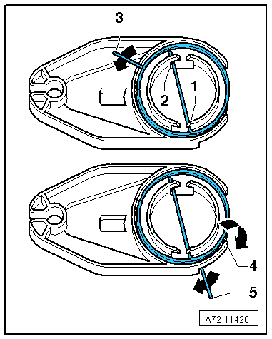
Release Cable Retainer With Installed Spring for Left Seat
- Attach the spring at points -1 and 2-.
- Turn the spring -3- clockwise.
- Place the spring around tab -4- so that it is touching -5-.
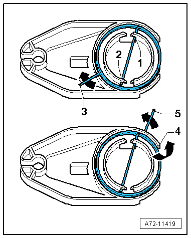
Release Cable Retainer with Installed Spring for Right Seat
- Attach the spring at points -1 and 2-.
- Turn the spring -3- counter-clockwise.
- Place the spring around tab -4- so that it is touching -5-.
Installation notes, for example tightening specifications, replacing components. Refer to → Chapter "Overview - Seat Pan, Seat Forward/Back Adjustment".