Audi A6 Typ 4G: Glove Compartment Handle, Removing and Installing
Special tools and workshop equipment required
- Locking Pin (3 pc.) -T40011-
Removing
 Note
Note
If glove compartment cover does not open, it can be opened via the emergency release. Refer to → Chapter "Glove Compartment Lid Emergency Release, Operating".
Vehicles with Knee Airbag
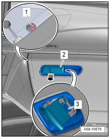
- Open the glove compartment and remove the bolt -1-.
- Press the glove compartment handle -2- and release retaining the hook -3- at the side of the glove compartment opener using a screwdriver.
- Remove the glove compartment opener from the glove compartment cover -arrow-.
Vehicles without Knee Airbags
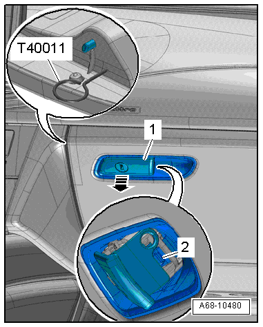
- Press the glove compartment handle -1- and release retaining the hook -2- at the side of the glove compartment opener using a screwdriver.
- Insert the Locking Pin (3 pc.) -T40011- through an opening on the side of the glove compartment lid and release the hook in the glove compartment handle.
- Remove the glove compartment opener from the glove compartment cover -arrow-.
Installing
Install in reverse order of removal. Note the following:
Installation notes, for example tightening specifications, replacing components. Refer to → Chapter "Overview - Glove Compartment".
Glove Compartment, Removing and Installing
Glove Compartment Lid Emergency Release, Operating
Special tools and workshop equipment required
- Hex Ball Socket -T10058-
Procedure
- Remove the front passenger side instrument panel side cover. Refer to → Chapter "Instrument Panel Side Cover, Removing and Installing".
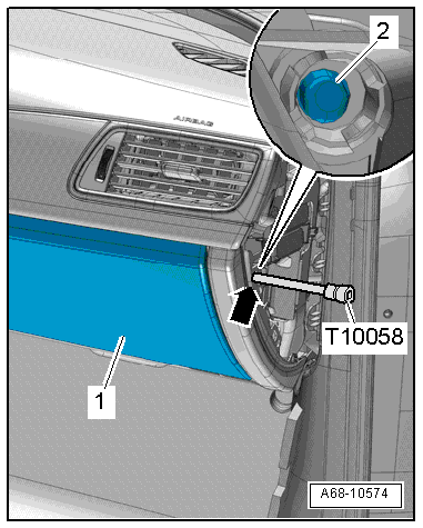
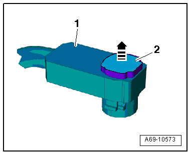
- Insert a Hex Ball Socket -T10058- (or another suitable tool 80 mm long) through the opening -arrow- on the front passenger side instrument panel.
- Open glove compartment cover -1- by pressing down locking pin -2-.
Glove Compartment, Removing and Installing
Removing
Note
If glove compartment cover does not open, it can be opened via the emergency release. Refer to → Chapter "Glove Compartment Lid Emergency Release, Operating".
- Disconnect the battery Ground (GND) cable with the ignition turned on. Refer to → Electrical Equipment; Rep. Gr.27; Battery; Battery, Disconnecting and Connecting.
- Equipment level with DVD/CD changer: remove the DVD/CD changer. Refer to → Communication; Rep. Gr.91; DVD/CD Changer.
- Vehicles versions with Chip Card Reader Control Module -J676-: remove the Chip Card Reader Control Module -J676-. Refer to → Comunication; Rep. Gr.91; Navigation System; Chip Card Reader Control Module, Removing and Installing.
- Remove the side instrument panel cover on the passenger side. Refer to → Chapter "Instrument Panel Side Cover, Removing and Installing".
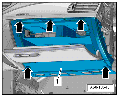
- Open the glove compartment cover and remove the screws -arrows-.
 WARNING
Before handling pyrotechnic components (for example, disconnecting the connector), the person handling it must "discharge static electricity". This can be done by touching the door striker, for example.
- Remove glove compartment -1- just far enough until it is possible to disconnect the connector from the central connector.
Installing
WARNING
- Before handling pyrotechnic components (for example, connecting the connector), the person handling it must "discharge static electricity". This can be done by touching the door striker, for example.
- Make sure the connectors are installed correctly and are secure.
Install in reverse order of removal. Note the following:
- Press the electrical connector together until it engages audibly.
WARNING
Ignition must be on when connecting battery. If pyrotechnic components (for example, airbag, belt tensioner) are not repaired correctly, they may deploy unintentionally after connecting battery. There must not be anyone inside the vehicle when connecting the battery.
DANGER!
When working on vehicles with the ignition already switched on or that are ready to drive there is a danger of the engine starting unexpectedly and of being poisoned by gas in enclosed areas. Risk of body parts and/or clothing being clamped or pulled.
Perform the following before switching on the ignition:
- Move the selector lever into P.
- Activate the parking brake
- Turn off the ignition.
- Open the hood
- Connect the charger, such as the Battery Charger -VAS5095A- to the jump start of the 12V vehicle electrical system.
- Turn on the ignition.
- Connect the battery GND cable with the ignition turned on. Refer to → Electrical Equipment; Rep. Gr.27; Battery; Battery, Disconnecting and Connecting.
Note
If the Airbag Indicator Lamp -K75- indicates a fault, check the Diagnostic Trouble Code (DTC) memory, erase it and check it again. Refer to Vehicle Diagnostic Tester.
Installation notes, for example tightening specifications, replacing components. Refer to → Chapter "Overview - Glove Compartment".
Glove Compartment, Removing and Installing, with Knee Airbag
Removing
Note
If glove compartment cover does not open, it can be opened via the emergency release. Refer to → Chapter "Glove Compartment Lid Emergency Release, Operating".
WARNING
- Follow all Safety Precautions when working with pyrotechnic components. Refer to → Chapter "Pyrotechnic Components Safety Precautions".
- Follow all regulations when disposing of pyrotechnic components. Refer to → Chapter "Airbag, Belt Tensioner and Battery Cut-Out Units, Storing, Transporting and Disposing".
- Disconnect the battery Ground (GND) cable with the ignition turned on. Refer to → Electrical Equipment; Rep. Gr.27; Battery; Battery, Disconnecting and Connecting.
- Equipment level with DVD/CD changer: remove the DVD/CD changer. Refer to → Communication; Rep. Gr.91; DVD/CD Changer.
- Vehicles versions with Chip Card Reader Control Module -J676-: remove the Chip Card Reader Control Module -J676-. Refer to → Comunication; Rep. Gr.91; Navigation System; Chip Card Reader Control Module, Removing and Installing.
- Remove the side instrument panel cover on the passenger side. Refer to → Chapter "Instrument Panel Side Cover, Removing and Installing".
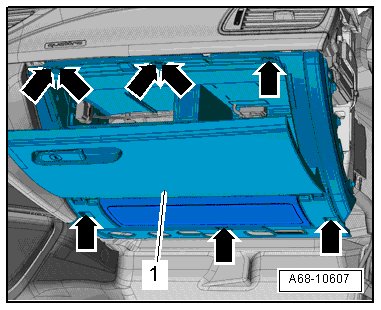
- Open the glove compartment cover and remove the screws -arrows-.
WARNING
Before handling pyrotechnic components (for example, disconnecting the connector), the person handling it must "discharge static electricity". This can be done by touching the door striker, for example.
- Remove glove compartment -1- just far enough until it is possible to disconnect the connector from the central connector.
- Disconnect the yellow knee airbag electrical connector.
- Release the connector lock -2- with a small screwdriver in direction of -arrow- and disconnect the connector -1-.
- Remove the glove compartment and the knee airbag.
WARNING
Set the glove compartment down so the padding on the knee airbag faces up.
Installing
WARNING
- Follow all Safety Precautions when working with pyrotechnic components. Refer to → Chapter "Pyrotechnic Components Safety Precautions".
- Before handling pyrotechnic components (for example, connecting the connector), the person handling it must "discharge static electricity". This can be done by touching the door striker, for example.
- Make sure the connectors are installed correctly and are secure.
Install in reverse order of removal. Note the following:
- Press the electrical connector together until it engages audibly.
WARNING
Ignition must be on when connecting battery. If pyrotechnic components (for example, airbag, belt tensioner) are not repaired correctly, they may deploy unintentionally after connecting battery. There must not be anyone inside the vehicle when connecting the battery.
DANGER!
When working on vehicles with the ignition already switched on or that are ready to drive there is a danger of the engine starting unexpectedly and of being poisoned by gas in enclosed areas. Risk of body parts and/or clothing being clamped or pulled.
Perform the following before switching on the ignition:
- Move the selector lever into P.
- Activate the parking brake
- Turn off the ignition.
- Open the hood
- Connect the charger, such as the Battery Charger -VAS5095A- to the jump start of the 12V vehicle electrical system.
- Turn on the ignition.
- Connect the battery GND cable with the ignition turned on. Refer to → Electrical Equipment; Rep. Gr.27; Battery; Battery, Disconnecting and Connecting.
Note
If the Airbag Indicator Lamp -K75- indicates a fault, check the Diagnostic Trouble Code (DTC) memory, erase it and check it again. Refer to Vehicle Diagnostic Tester.
Installation notes, for example tightening specifications, replacing components. Refer to → Chapter "Overview - Glove Compartment".
Storage Compartment, Removing and Installing
Removing
Note
If glove compartment cover does not open, it can be opened via the emergency release. Refer to → Chapter "Glove Compartment Lid Emergency Release, Operating".
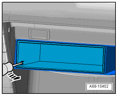
- Release the left and right retaining hooks using a screwdriver -arrow- and remove the storage compartment from the glove compartment.
Installing
Install in reverse order of removal. Note the following:
Installation notes, for example tightening specifications, replacing components. Refer to → Chapter "Overview - Glove Compartment".
Glove Compartment Lid, Removing and Installing
Removing
- Remove the glove compartment. Refer to → Chapter "Glove Compartment, Removing and Installing".
- Remove the hinge pin from the brake component. Refer to → Chapter "Glove Compartment Lid Dampening Mechanism, Removing and Installing".
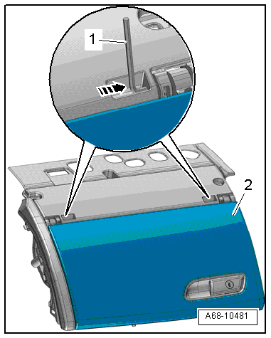
- Set the glove compartment down with the top side on a soft surface.
- Drive the left and right hinge pins out using a 4 mm hex socket wrench -1- (or another suitable tool) -arrow-.
- Remove glove compartment cover -2- from the glove compartment.
Installing
Install in reverse order of removal. Note the following:
Installation notes, for example tightening specifications, replacing components. Refer to → Chapter "Overview - Glove Compartment".
Glove Compartment Lid Dampening Mechanism, Removing and Installing
Removing
- Remove the glove compartment. Refer to → Chapter "Glove Compartment, Removing and Installing".
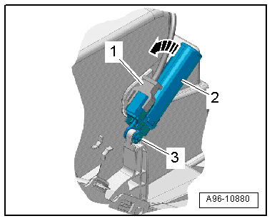
- Disconnect the connector -1-.
- Remove the hinge pins -3-.
- Release the lid dampening mechanism -2- by turning counterclockwise -arrow- and remove it.
Installing
Install in reverse order of removal. Note the following:
Installation notes, for example tightening specifications, replacing components. Refer to → Chapter "Overview - Glove Compartment".