Audi A6 Typ 4G: Headlamp, Adjusting
Headlamp, Adjusting
- The following test and adjustment description applies to all countries.
- However, national guidelines or regulations of the country should be observed.
LED Headlamp, Adjusting, all Vehicles from MY 2015
Checking and Adjusting Conditions
- Tire pressure is OK.
- The headlamp lens must be clean and dry.
- The headlamp lens may not be damaged.
- Headlamp-reflector and lamp OK.
Vehicles with Steel Suspension:
- Vehicle load must be created.
Vehicle load on driver's seat in otherwise unloaded vehicle (curb weight).
- One person or 75 kg (165.34 lbs).
The curb weight is the weight of the operational vehicle with completely full fuel tank, including the weight of all equipment carried in operation.
- Fuel tank: at least 90% full.
- Equipment: for example, spare wheel, tools, vehicle jack, fire extinguisher, etc.
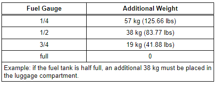
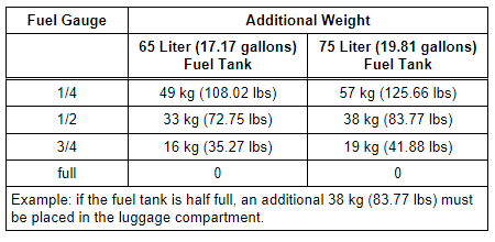
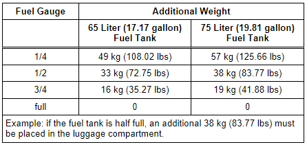
If the fuel tank is not at least 90% full, the load must be created as follows.
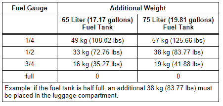
- Check fuel tank fill lever in instrument cluster tank gauge and compare with the following table. Place additional weight in the luggage compartment, if necessary.
 Note
Note
Use fuel containers filled with water as additional weight (a five liter fuel container filled with water weighs five kg (11 lbs) ).
Vehicles with Air Suspension:
- The compressed air reservoir must be filled. Start the engine and let it run in the neutral position for approximately two minutes.
All Vehicles:
- The electromechanical parking brake must not be engaged so vehicle is not under stress.
- The vehicle and headlamp adjusting unit must be on a level surface.
- Headlamp adjusting unit must be aligned to the vehicle. To do this, slide the headlamp adjusting unit a distance of 100 mm centered in front of the vehicle and aligned to the vehicle front. Refer to Headlamp Adjusting Unit Operating Instructions.
- Slide the headlamp adjusting unit in front of the corresponding headlamp and check the alignment again.
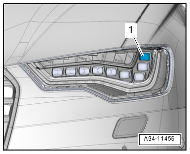
- LED and Matrix LED headlamp: The headlamp adjusting unit must be aligned at the center of the marked reference segment -1-.
- The inclination dimension is set on the headlamp adjusting unit. Refer to the Headlamp Adjusting Unit Operating Instructions.
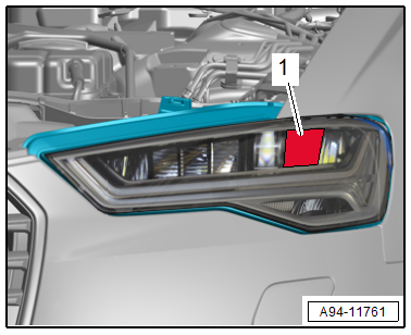
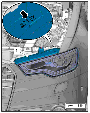
- The angle dimension -arrow- is stamped for ECE countries on the upper edge of the headlamp -1- in "%".
- The standard angle dimension for the USA is 0.7%.
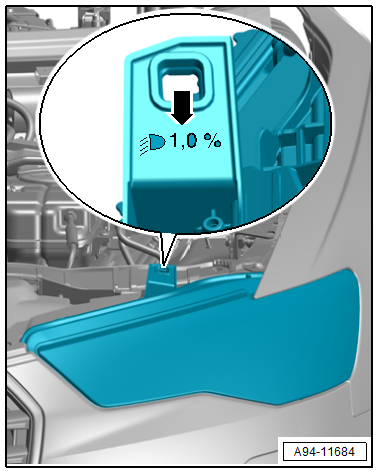
Note
The percentage indicator is based on a 10 meter projection distance. At an angle dimension of 1.0%, for example, converts to 10 cm.
Preliminary Work
- Turn the headlamp switch to "low beam" - not "Auto".
- Close all the doors and the rear lid and keep them closed for the duration of the testing/adjusting procedure.
Procedure
- Connect the Vehicle Diagnostic Tester.
- Select the Diagnostic mode and start the diagnostics.
- Select the tab test plan.
- Select select individual tests and choose the following sequence.
Vehicles without Matrix-Beam
- Body
- Electrical Equipment
- 01 - OBD-capable systems
- 09 - Electronic central electrical J519
- 09 - Vehicle Electrical System Control Module, functions
- 09 - Headlamp basic setting (Rep.-Gr. 94)
Vehicles with Matrix-Beam
- Body
- Electrical Equipment
- 01 - OBD-capable systems
- 55 - Dynamic headlamp beam adjustment (MxB) J431
- 55 - Headlamp range control, functions
- 55 - Matrixbeam basic setting (repair group 94)
Note
- The headlamps move into the basic setting with this program.
- If the vehicle has air suspension, the suspension will move into the air suspension normal level at the same time.
- Continue to follow the instructions in the Vehicle Diagnostic Tester display.
- During the program, you will be asked to perform a headlamp adjustment.
Headlamp Adjustment
Note
The image and the following description apply to the headlamp adjusting unit. Pay attention to the Owner's Manual for the digital headlamp adjusting units for example Headlamp Adjusting Unit -VAS5209B- or Headlamp Adjusting Unit -VAS621001-. Refer to the Headlamp Adjusting Unit Owner's Manual.
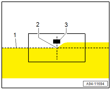
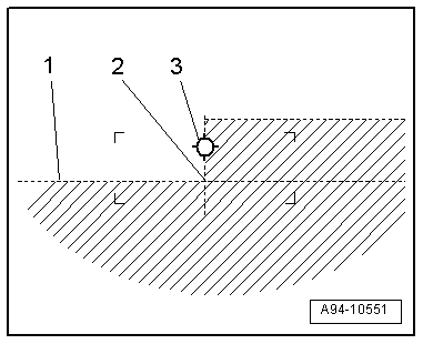
- The horizontal light-dark border must touch the dividing line -1- on the adjusting unit test surface.
- The point -2- between the left horizontal part and the right rising part of the light-dark border must run vertically through the central mark -3-. The bright core of the light beam must be to the right of the vertical.
Note
- To determine the bend point -2- more easily, cover and uncover the left half of the headlamp (seen in direction of travel) several times. Then check the low beam again.
- After adjusting the low beam according to the instructions, the center of the high beam light beam must be on the central marking -3-.
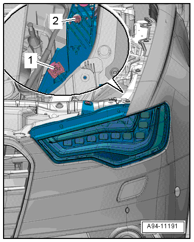
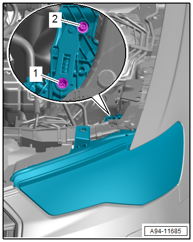
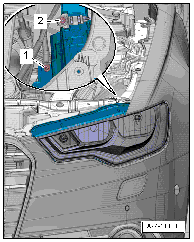
- Pry off cap (if applicable) off the adjusting screw for adjusting the height.
- To adjust the height of the headlamp, set the light-dark border just above the dividing line with the adjustment screw -1-.
- Then adjust the light-dark border, starting from the top, on the dividing line.
- For side adjustment, turn the adjusting screw -2-.
Note
The allocation on the right headlamp is reversed.
- After the headlamp adjustment has been successful, follow the instructions on the Vehicle Diagnostic Tester display in order to leave the air suspension normal level.
Note
If the program get interrupted, then the air suspension normal level must be deactivated manually. Refer to → Suspension, Wheels, Steering; Rep. Gr.43; Electronic Damping.
- Disconnect the diagnostic connector.
Halogen Headlamp, Adjusting
Checking and Adjusting Conditions
- Tire pressure is OK.
- The headlamp lens must be clean and dry.
- The headlamp lens may not be damaged.
- Headlamp reflectors and bulbs are OK.
- Vehicle load must be created.
Vehicle load on driver's seat in otherwise unloaded vehicle (curb weight).
- One person or 75 kg (165.34 lbs).
The curb weight is the weight of the operational vehicle with completely full fuel tank, including the weight of all equipment carried in operation.
- Fuel tank: at least 90% full.
- Equipment: for example, spare wheel, tools, vehicle jack, fire extinguisher, etc.
If the fuel tank is not at least 90% full, the load must be created as follows.
- Check fuel tank fill lever in instrument cluster tank gauge and compare with the following table. Place additional weight in the luggage compartment, if necessary.
Note
Use fuel containers filled with water as additional weight (a five liter fuel container filled with water weighs five kg (11.02 lbs).
- The electro-mechanical parking brake must not be engaged so that the vehicle is not under stress.
- The vehicle and headlamp adjusting unit must be on a level surface.
- The headlamp adjusting unit must be aligned to the vehicle. To do this, slide the headlamp adjusting unit a specified distance of centered in front of the vehicle and aligned to the vehicle front. Refer to Headlamp Adjusting Owner's Manual.
- Slide the headlamp adjusting unit in front of the corresponding headlamp and check the alignment again.
- The angle dimension is set on the headlamp adjusting unit. Refer to the Headlamp Adjusting Unit Operating Instructions.
- The angle dimension -arrow- is stamped for ECE countries on the upper edge of the headlamp -1- in "%".
- The standard angle dimension for the USA is 0.7%.
Note
The percentage indicator is based on a 10 meter projection distance. At an angle dimension of 1.0%, for example, converts to 10 cm.
Preliminary Work
- Turn the headlamp switch to "low beam" - not "Auto".
- Set the range position thumbwheel to the "0" position.
Headlamp Adjustment
- The horizontal light-dark border must touch the dividing line -1- on the adjusting unit test surface.
- The point -2- between the left horizontal part and the right vertical part of the light-dark border must run vertically through the central mark -3-. The bright core of the light beam must be to the right of the vertical.
Note
- To determine the point -2- more easily, cover and uncover the left half of the headlamp several times. Then check low beam again.
- After correct headlamp adjustment, the center of the high beam light beam must be on the central marking -3-.
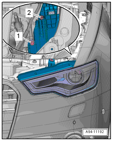
- To adjust the height of the headlamp, set the light-dark border just under the dividing line with the adjustment screw -1-.
- Then adjust the light-dark border, starting from the bottom, on the dividing line.
- For side adjustment, turn the adjusting screw -2-.
Note
The allocation on the right headlamp is reversed.
HID Headlamps, Adjusting, through MY 2014
Checking and Adjusting Conditions
- Tire pressure is OK.
- The headlamp lens must be clean and dry.
- The headlamp lens may not be damaged.
- Headlamp reflectors and bulbs are OK.
Vehicles with Steel Suspension:
- Vehicle load must be created.
Vehicle load on driver's seat in otherwise unloaded vehicle (curb weight).
- One person or 75 kg (165.34 lbs).
The curb weight is the weight of the operational vehicle with completely full fuel tank, including the weight of all equipment carried in operation.
- Fuel tank: at least 90% full.
- Equipment: for example, spare wheel, tools, vehicle jack, fire extinguisher, etc.
If the fuel tank is not at least 90% full, the load must be created as follows.
- Check fuel tank fill lever in instrument cluster tank gauge and compare with the following table. Place additional weight in the luggage compartment, if necessary.
Note
Use fuel containers filled with water as additional weight (a five liter fuel container filled with water weighs five kg (11.02 lbs) ).
Vehicles with Air Suspension:
- The compressed air reservoir must be filled. Start the engine and let it run at idle for approximately 2 minutes.
All Vehicles:
- The electro-mechanical parking brake must not be engaged so that the vehicle is not under stress.
- The vehicle and headlamp adjusting unit must be on a level surface.
- The headlamp adjusting unit must be aligned to the vehicle. To do this, slide the headlamp adjusting unit a specified distance of centered in front of the vehicle and aligned to the vehicle front. Refer to Headlamp Adjusting Owner's Manual.
- Slide the headlamp adjusting unit in front of the corresponding headlamp and check the alignment again.
- The angle dimension is set on the headlamp adjusting unit. Refer to the Headlamp Adjusting Unit Operating Instructions.
- The angle dimension -arrow- is stamped for ECE countries on the upper edge of the headlamp -1- in "%".
- The standard angle dimension for the USA is 0.7%.
Note
The percentage indicator is based on a 10 meter projection distance. At an angle dimension of 1.0%, for example, converts to 10 cm.
Procedure
- Turn the headlamp switch to "low beam" - not "Auto".
- Close all the doors and the rear lid and keep them closed for the duration of the testing/adjusting procedure.
Procedure
- Connect the Vehicle Diagnostic Tester.
- Select the Diagnostic mode and start the diagnostics.
- Select the tab test plan.
- Select select individual tests and choose the following sequence.
- Body
- Electrical Equipment
- 01 - OBD-capable systems
- 55 - Dynamic headlamp range control - J431/J745
- 55 - Headlamp range control, functions
- 55 - Basic setting
Note
- The headlamps move into the basic setting with this program.
- If the vehicle has air suspension, the suspension will move into the air suspension normal level at the same time.
- Follow the instructions on the Vehicle Diagnostic Tester display.
- During the program, you will be asked to perform a headlamp adjustment.
Headlamp Adjustment
- The horizontal light-dark border must touch the dividing line -1- on the adjusting unit test surface.
- The point -2- between the left horizontal part and the right vertical part of the light-dark border must run vertically through the central mark -3-. The bright core of the light beam must be to the right of the vertical.
Note
- To determine the point -2- more easily, cover and uncover the left half of the headlamp several times. Then check low beam again.
- After correct headlamp adjustment, the center of the high beam light beam must be on the central marking -3-.
- Pry off cap (if applicable) off the adjusting screw for adjusting the height.
- To adjust the height of the headlamp, set the light-dark border just above the dividing line with the adjustment screw -1-.
- Then adjust the light-dark border, starting from the top, on the dividing line.
- For side adjustment, turn the adjusting screw -2-.
Note
The allocation on the right headlamp is reversed.
- After the headlamp adjustment has been successful, follow the instructions on the Vehicle Diagnostic Tester display in order to leave the air suspension normal level.
Note
If the program get interrupted, then the air suspension normal level must be deactivated manually. Refer to → Suspension, Wheels, Steering; Rep. Gr.43; Electronic Damping.
- Disconnect the diagnostic connector.
LED Headlamps, Adjusting, through MY 2014
Checking and Adjusting Conditions
- Tire pressure is OK.
- The headlamp lens must be clean and dry.
- The headlamp lens may not be damaged.
- Headlamp reflectors and bulbs are OK.
Vehicles with Steel Suspension:
- Vehicle load must be created.
Vehicle load on driver's seat in otherwise unloaded vehicle (curb weight).
- One person or 75 kg (165.34 lbs)
The curb weight is the weight of the operational vehicle with completely full fuel tank, including the weight of all equipment carried in operation.
- Fuel tank: at least 90% full.
- Equipment: for example, spare wheel, tools, vehicle jack, fire extinguisher, etc.
If the fuel tank is not at least 90% full, the load must be created as follows.
- Check fuel tank fill lever in instrument cluster tank gauge and compare with the following table. Place additional weight in the luggage compartment, if necessary.
Note
Use fuel containers filled with water as additional weight (a five liter fuel container filled with water weighs five kg (11.02 lbs) ).
Vehicles with Air Suspension:
- The compressed air reservoir must be filled. Start the engine and let it run at idle for approximately 2 minutes.
All Vehicles:
- The electro-mechanical parking brake must not be engaged so that the vehicle is not under stress.
- The vehicle and headlamp adjusting unit must be on a level surface.
- The headlamp adjusting unit must be aligned to the vehicle. To do this, slide the headlamp adjusting unit a specified distance of centered in front of the vehicle and aligned to the vehicle front. Refer to → Headlamp Adjusting Owner's Manual.
- Slide the headlamp adjusting unit in front of the corresponding headlamp and check the alignment again.
- The angle dimension is set on the headlamp adjusting unit. Refer to the → Headlamp Adjusting Unit Operating Instructions.
- The angle dimension -arrow- is stamped for ECE countries on the upper edge of the headlamp -1- in "%".
- The standard angle dimension for the USA is 0.7%.
Note
The percentage indicator is based on a 10 meter projection distance. At an angle dimension of 1.0%, for example, converts to 10 cm.
Preliminary Work
- The vehicle must be standing on a flat surface.
- Turn the headlamp switch to "low beam" - not "Auto".
- Close all the doors and the rear lid and keep them closed for the duration of the testing/adjusting procedure.
Procedure
- Connect the Vehicle Diagnostic Tester.
- Select the Diagnostic mode and start the diagnostics.
- Select the tab test plan.
- Select select individual tests and choose the following sequence.
- Body
- Electrical Equipment
- 01 - OBD-capable systems
- 55 - Headlamp Range Control Module - J431/J745
- 55 - Headlamp range control, functions
- 55 - Basic setting
Note
- The headlamps move into the basic setting with this program.
- If the vehicle has air suspension, the suspension will move into the air suspension normal level at the same time.
- Follow the instructions on the Vehicle Diagnostic Tester display.
- During the program, you will be asked to perform a headlamp adjustment.
Headlamp Adjustment
- The headlamp setting unit must be aligned to the uppermost LED lens -1-.
- The horizontal light-dark border must touch the dividing line -1- on the adjusting unit test surface.
- The point -2- between the left horizontal part and the right vertical part of the light-dark border must run vertically through the central mark -3-. The bright core of the light beam must be to the right of the vertical.
Note
- To determine the point -2- more easily, cover and uncover the left half of the headlamp several times. Then check low beam again.
- After correct headlamp adjustment, the center of the high beam light beam must be on the central marking -3-.
- To adjust the height of the headlamp, set the light-dark border just above the dividing line with the adjustment screw -1-.
- Then adjust the light-dark border, starting from the top, on the dividing line.
- For side adjustment, turn the adjusting screw -2-.
Note
The allocation on the right headlamp is reversed.