Audi A6 Typ 4G: Matrix LED Headlamp, Calibrating
Matrix LED Headlamp, Calibrating with Headlamp Adjusting Unit -VAS5209B-
Special tools and workshop equipment required
- Headlamp Adjusting Unit -VAS5209B-
 Note
Note
- The Matrix LED headlamp is calibrated using the Vehicle Diagnostic Tester.
- In this procedure the low beam is set first. Then the calibration of the Matrix-beam-high beam light calibration is performed.
Note
Software version from V 0.80 for the Headlamp Adjusting Unit -VAS5209B- is required to calibrate the Matrix-beam-high beam light.
After the following Work the Matrix Headlamp Must Be Calibrated:
- Headlamp position was changed (removing and installing, loosening and tightening)
- Headlamp Range Control Module -J431- was replaced.
- The rear axle toe was adjusted.
- The DTC "no or incorrect basic setting/adaptation" is stored in the DTC memory.
Requirements
- Follow the complete test and adjustment requirements. Refer to → Chapter "Headlamp, Adjusting".
Procedure
- Align the Headlamp Adjusting Unit -VAS5209B- at the distance -a- = 100 mm to the vehicle center. Refer to the Headlamp Adjusting Unit -VAS5209B- Owner's Manual.

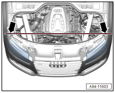
- Check the parallel alignment of the headlamp adjusting unit -VAS5209B- to the vehicles transverse axis, to do this align the Headlamp Adjusting Unit -VAS5209B- laser beam on the front left and right fender bolts -arrows-.
- Push the Headlamp Adjusting Unit -VAS5209B- in front of the front left headlamp to check the parallel alignment again.
 Caution
There is a risk of glaring other drivers due to incorrect alignment of the headlamp adjusting unit.
Place particular value on the correct alignment of the headlamp adjusting unit. Only when this is successful, can the headlamps be adjusted so that other drivers are not glared.
Performing Calibration
Vehicle Diagnostic Tester is attached.
- Select the Diagnostic mode and start the diagnostics.
- Select the tab test plan.
- Select select individual tests and choose the following sequence.
- Body
- Electrical Equipment
- 01 - OBD-capable systems
- 55 - Dynamic headlamp beam adjustment (MxB) - J431
- 55 - Headlamp range control, functions
- 55 - Matrixbeam basic setting (repair group 94)
From here using the Vehicle Diagnostic Tester advances the calibration procedure forward. For this procedure the low beam must be adjusted first. Refer to → Chapter "LED Headlamp, Adjusting, all Vehicles from MY 2015".
In the continued program sequence a request is made to determine/read and to input the angle value of the inner segment edge of the left headlamp in the headlamp adjusting unit.
- Position the light collecting box lens on the center of the headlamp a reference segment.
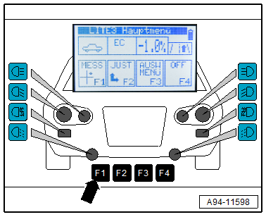
- In the main menu of the Headlamp Adjusting Unit -VAS5209B- press the "F1"-button -arrow- to measure the angle value.
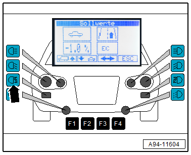
Shown on display:
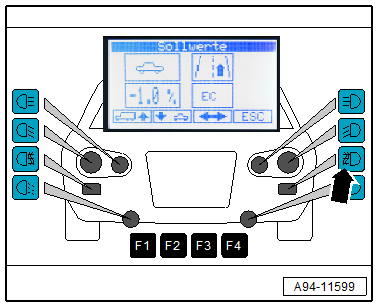
- Push the button -arrow- for the left fog lamp for at least three seconds.
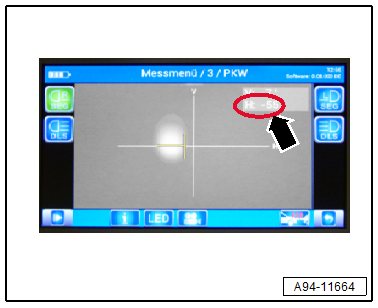
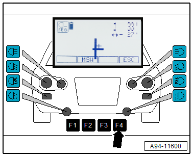
Shown on display:
- The angle values of the inner reference segment edge are displayed.
- Enter the angle value -arrow- of the inner reference segment edge in the Vehicle Diagnostic Tester, while doing this if necessary pay attention to the sign.
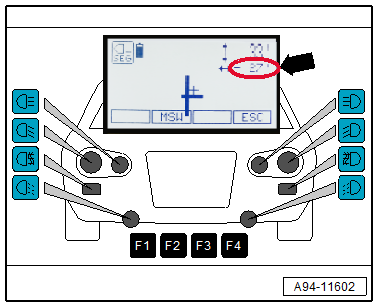
- Push the "F4"-button -arrow- on the Headlamp Adjusting Unit -VAS5209B-.
In the continued program sequence a request is made to determine/read and to input the angle value of the inner segment edge of the right headlamp in the headlamp adjusting unit.
- Align the headlamp adjusting unit Headlamp Adjusting Unit -VAS5209B- at the distance -a- = 100 mm to the vehicle center. Refer to the Headlamp Adjusting Unit -VAS5209B- Owner's Manual.
- Check the parallel alignment of the Headlamp Adjusting Unit -VAS5209B- to the vehicles transverse axis, to do this align the Headlamp Adjusting Unit -VAS5209B- laser beam on the front left and right fender bolts -arrows-.
- Push the Headlamp Adjusting Unit -VAS5209B- in front of the front right headlamp to check the parallel alignment again.
- Position the light collecting box lens on the center of the headlamp a reference segment.
- In the main menu of the Headlamp Adjusting Unit -VAS5209B- press the "F1"-button -arrow- to measure the angle value.
Shown on display:
- Push the button -arrow- for the right fog lamp for at least three seconds.
Shown on display:
- The angle values of the inner reference segment edge are displayed.
- Enter the angle value -arrow- of the inner reference segment edge in the Vehicle Diagnostic Tester, while doing this if necessary pay attention to the sign.
- Push the "F4"-button -arrow- on the Headlamp Adjusting Unit -VAS5209B-.
- After completing the calibration read the DTC memory and correct any existing faults.
Matrix LED Headlamp, Calibrating with Headlamp Adjusting Unit -VAS621001-
Special tools and workshop equipment required
- Headlamp Adjusting Unit -VAS621001-
Note
- The Matrix LED headlamp is calibrated using the Vehicle Diagnostic Tester.
- In this procedure the low beam is set first. Then the calibration of the Matrix-beam-high beam light calibration is performed.
After the following Work the Matrix Headlamp Must Be Calibrated:
- Headlamp position was changed (removing and installing, loosening and tightening)
- Headlamp Range Control Module -J431- was replaced.
- The rear axle toe was adjusted.
- The DTC "no or incorrect basic setting/adaptation" is stored in the DTC memory.
Requirements
- Follow the complete test and adjustment requirements → Chapter "Headlamp, Adjusting".
Procedure
- Align the Headlamp Adjusting Unit -VAS621001- at the distance -a- = 100 mm to the vehicle center. Refer to the Headlamp Adjusting Unit -VAS621001- Owner's Manual.
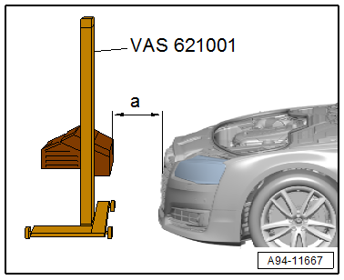
- Check the parallel alignment of the headlamp adjusting unit -VAS621001- to the vehicles transverse axis, to do this align the Headlamp Adjusting Unit -VAS621001- laser beam on the front left and right fender bolts -arrows-.
- Push the Headlamp Adjusting Unit -VAS621001- in front of the front left headlamp to check the parallel alignment again.
Caution
There is a risk of glaring other drivers due to incorrect alignment of the headlamp adjusting unit.
Place particular value on the correct alignment of the headlamp adjusting unit. Only when this is successful, can the headlamps be adjusted so that other drivers are not glared.
Performing calibration
Vehicle Diagnostic Tester is attached.
- Select the Diagnostic mode and start the diagnostics.
- Select the tab test plan.
- Select select individual tests and choose the following sequence.
- Body
- Electrical Equipment
- 01 - OBD-capable systems
- 55 - Dynamic headlamp beam adjustment (MxB) - J431
- 55 - Headlamp range control, functions
- 55 - Matrixbeam basic setting (repair group 94)
From here using the Vehicle Diagnostic Tester advances the calibration procedure forward. For this procedure the low beam must be adjusted first. Refer to → Chapter "LED Headlamp, Adjusting, all Vehicles from MY 2015".
In the continued program sequence a request is made to determine/read and to input the angle value of the inner segment edge of the left headlamp in the headlamp adjusting unit.
- Position the light collecting box lens on the center of the headlamp a reference segment.
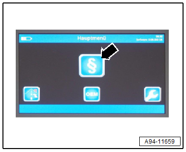
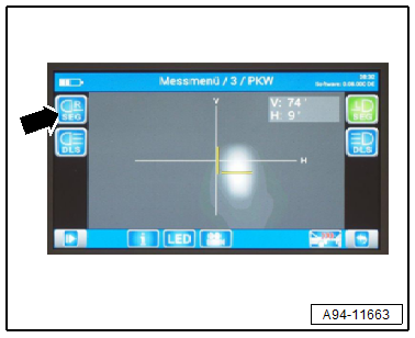
- To do so on the Headlamp Adjusting Unit -VAS621001- in the main menu press the "§"- button -arrow- to start the measurement procedure.
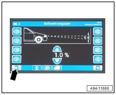
Shown on display:
- Push the button -arrow- twice and wait until the light measurement is active.
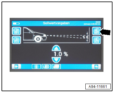
Shown on display:
- Press the button -arrow-.
- Wait until the light measurement is complete.
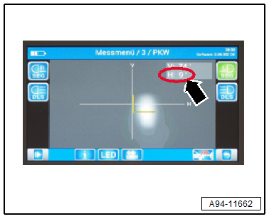
Shown on display:
- The angle values of the inner reference segment edge are displayed.
- Enter the angle value -arrow- of the inner reference segment edge in the Vehicle Diagnostic Tester, while doing this if necessary pay attention to the sign.
In the continued program sequence a request is made to determine/read and to input the angle value of the inner segment edge of the right headlamp in the headlamp adjusting unit.
- Align the Headlamp Adjusting Unit -VAS621001- at the distance -a- = 100 mm to the vehicle center. Refer to the Headlamp Adjusting Unit -VAS621001- Owner's Manual.
- Check the parallel alignment of the Headlamp Adjusting Unit -VAS621001- to the vehicles transverse axis, to do this align the Headlamp Adjusting Unit -VAS621001- laser beam on the front left and right fender bolts -arrows-.
- Push the Headlamp Adjusting Unit -VAS621001- in front of the front right headlamp to check the parallel alignment again.
- Position the light collecting box lens on the center of the headlamp a reference segment.
Shown on display:
- Press the button -arrow-.
- Wait until the light measurement is complete.
Shown on display:
- The angle values of the inner reference segment edge are displayed.
- Enter the angle value -arrow- of the inner reference segment edge in the Vehicle Diagnostic Tester, while doing this if necessary pay attention to the sign.
- After completing the calibration read the DTC memory and correct any existing faults.