Audi A6 Typ 4G: Infotainment System Display, Removing and Installing
6.5 Inch Display with Kinematics, Removing and Installing
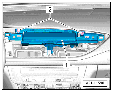
The Front Information Display Control Head -J685- (Display) is located in the center of the instrument panel.
Removing
- Turn off the ignition and all electrical consumers and remove the ignition key.
- Remove the center instrument vents. Refer to → Body Interior; Rep. Gr.70; Instrument Panel; Instrument Panel Vent, Removing and Installing.
Two screws for the kinematics are removed when the center vents are removed.
 Caution
Pay attention to the wire routing to the display in the instrument panel. It will not be possible to extend the display again if the wiring is routed incorrectly during installation.
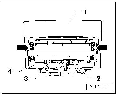
- Remove the screws -2- and pull the Front Information Display Control Head -J685--1- out of the instrument panel until the connectors on the rear side can be reached.
- Remove the clip -4- first, then disconnect the display connectors -1- and -3- and finally remove the clip -2-. Disconnect the engine -5- connector last.
- Completely remove the Front Information Display Control Head -J685- from the instrument panel.
Installing
- Install in reverse order of removal.
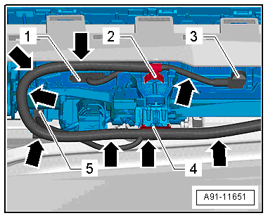
- Make sure that the wiring guide of the Front Information Display Control Head -J685- to the wiring harness and Information Electronics Control Module 1 -J794- is followed exactly -arrows-, otherwise the Front Information Display Control Head -J685- will not extend out.
- First install the clip in the center -2-, then connect the display connector -1- and -3- and then install the rear clip -4- and finally connect the engine connector -5-.
- Slide the Front Information Display Control Head -J685- into the instrument panel and tighten the screws -2- hand-tight.
After installing the center vents, align everything and tighten the screws.
8 Inch Display with Kinematics, Removing and Installing
The Front Information Display Control Head -J685- (Display) is located in the center of the instrument panel.
 Note
Note
- Only when the display is to be disconnected from the kinematics does the Front Information Display Control Head -J685- have to be brought into the service position before removal. Refer to → Chapter "8-Inch Front Display Service Position ".
- If only the display with kinematics should be removed and installed, then the service position for the Front Information Display Control Head -J685- is not necessary.
- If the Front Information Display Control Head -J685- was brought into the service position, the Vehicle Diagnostic Tester must remain connected.
Removing
- Turn off the ignition and all electrical consumers and remove the ignition key.
- Remove the center instrument vents. Refer to → Body Interior; Rep. Gr.70; Instrument Panel; Instrument Panel Vent, Removing and Installing.
Two screws for the kinematics are removed when the center vents are removed.
Caution
Pay attention to the wire routing to the display in the instrument panel. It will not be possible to extend the display again if the wiring is routed incorrectly during installation.
- Remove the screws -2- and pull the Front Information Display Control Head -J685--1- out of the instrument panel until the connectors on the rear side can be reached.
- Remove the clip -4- first, then disconnect the display connectors -1- and -3- and finally remove the clip -2-. Disconnect the engine -5- connector last.
- Completely remove the Front Information Display Control Head -J685- from the instrument panel.
Installing
- Install in reverse order of removal. Note the following:
- Make sure that the wiring guide of the Front Information Display Control Head -J685- to the wiring harness and Information Electronics Control Module 1 -J794- is followed exactly -arrows-, otherwise the Front Information Display Control Head -J685- will not extend out.
- First install the clip in the center -2-, then connect the display connector -1- and -3- and then install the rear clip -4- and finally connect the engine connector -5-.
- Slide the Front Information Display Control Head -J685- into the instrument panel and tighten the screws -2- hand-tight.
After installing the center vents, align everything and tighten the screws.
Front Display Front and Rear Cover, Removing and Installing
Caution
Danger of causing damage to the vehicle electronics
- Requirement: Make sure nothing, especially metal or other light weight particles, can get onto the display.
- Make sure also no oil, grease, silicone or other such materials can get onto the removed display, otherwise they can turn into steam and fog up the display.
- Touching electronic circuits with bare hands can lead to migration.
- ESD (electro static discharge) protection: Always follow standard DIN EN 613-40-5-1 when handling.
- Do not use any components or electronics that have fallen down.
- ESD Work Surface -VAS6613-. Refer to → Electrical Equipment General Information; Rep. Gr.97; ESD Work Surface VAS6613.
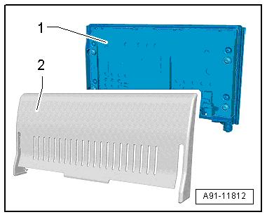
The Front Information Display Control Head -J685- can be disconnected from the kinematics. The front and rear covers can be replaced individually if they are scratched or faulty.
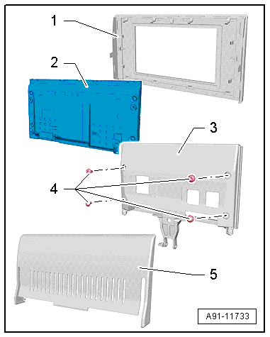
The Front Information Display Control Head -J685- consists of a front cover -1-, a display -2-, display support -3- and a rear cover -5-. The display and the display support are attached with screws -4- and the front and rear covers are clipped on.
The display is supplied installed with the mount. Refer to the Electronic Parts Catalog (ETKA). The front cover -1- and rear cover -5- can be ordered and replaced separately.
- Turn off the ignition and all electrical consumers and remove the ignition key.
Removing
- Remove the display with the kinematics:
- 6.5 inch. Refer to → Chapter "6.5 Inch Display with Kinematics, Removing and Installing".
- 8 inch. Refer to → Chapter "8 Inch Display with Kinematics, Removing and Installing".
First the Front Information Display Control Head -J685- is disconnected from the kinematics.
- Follow the guidelines for ESD (electro static discharge).
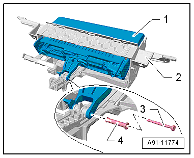
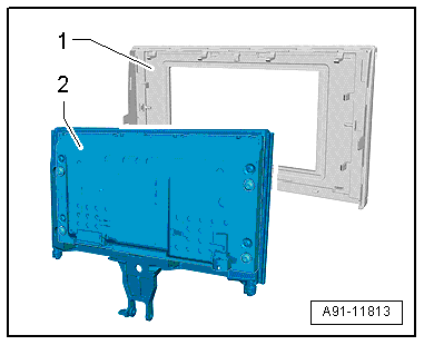
- Remove the mounting pin -3- and the bearing sleeve -4- from the display support -1-.
- Remove the display support -1- from the kinematics -2-.
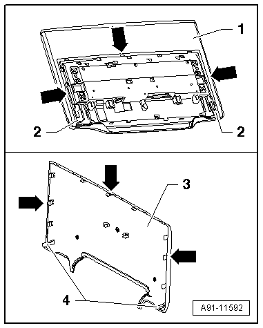
- Unclip the rear cover -2- from the display support with display -1-.
- Unclip the front cover -1- from the display support with display -2-.
Installing
- Install in reverse order of removal.
- Follow the guidelines for ESD (electro static discharge).
8-Inch Front Display Service Position
Bringing into the service position
Vehicle Diagnostic Tester is attached.
- Select the Diagnostic mode and start the diagnostics.
- Select select individual tests and choose the following sequence.
- Body
- Electrical Equipment
- 01 - OBD-capable systems
- 5F - Information electronics control module 1- J794
- 5F - Information electronics control module 1, functions
- 5F - Moving display pivot mechanism into service position
- Follow the instructions on the Vehicle Diagnostic Tester.
Multimedia Display Unit 1/2 -Y22-/-Y23-, Removing and Installing
Special tools and workshop equipment required
- Trim Removal Wedge -3409-
Removal and installation of Multimedia Display Unit 1 -Y22- and Multimedia Display Unit 2 -Y23- is identical.
Removing
- Turn off the ignition and all electrical consumers and remove the ignition key.
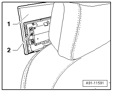
The display is attached to the front seat backrest by a retainer. It is not necessary to remove the retainer.
The display -1- is attached at the back with the cover -3-. Make sure the lower tabs -4- on the display -1- are pushed in first into the grooves -2-. Then install the other tabs -arrows-.
- Carefully unclip the cover -2- on the display -1- using the Trim Removal Wedge -3409--arrows-.
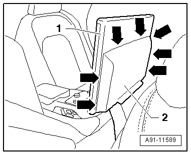
Two screws -arrows- attach the display -1- to the bracket -4-.
- Remove the bolts -2- and slide the display -1- upward slightly until the connectors lock into place.
- Unlock and disconnect the connectors -2- and -3- on the back on the display -1-.
- Remove the display upward completely from the bracket.
Installing
- Install in reverse order of removal.
The display -1- is attached at the back with the cover -3-. Make sure the lower tabs -4- on the display -1- are pushed in first into the grooves -2-. Then install the other tabs -arrows-.
