Audi A6 Typ 4G: Overview Selector Lever Handle
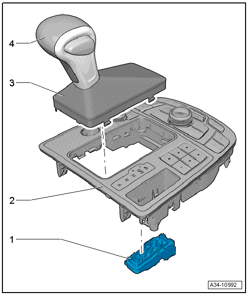
1 - Selector Lever Transmission Range Position Display Unit -Y26-
- Removing and Installing, refer to → Electrical Equipment; Rep. Gr.96; Lamps; Selector Lever Transmission Range Position Display Unit Y26, Removing and Installing.
2 - Multimedia System Control Head -E380-
- Removing and Installing, refer to → Communication; Rep. Gr.91; Infotainment System; Multimedia System Control Head E380, Removing and Installing.
3 - Selector Lever Boot
- Removing and installing together with the selector lever handle, refer to → Chapter "Selector Lever Handle, Removing and Installing"
4 - Selector Lever Handle
- Removing and installing, refer to → Chapter "Selector Lever Handle, Removing and Installing".
Overview - Selector Mechanism
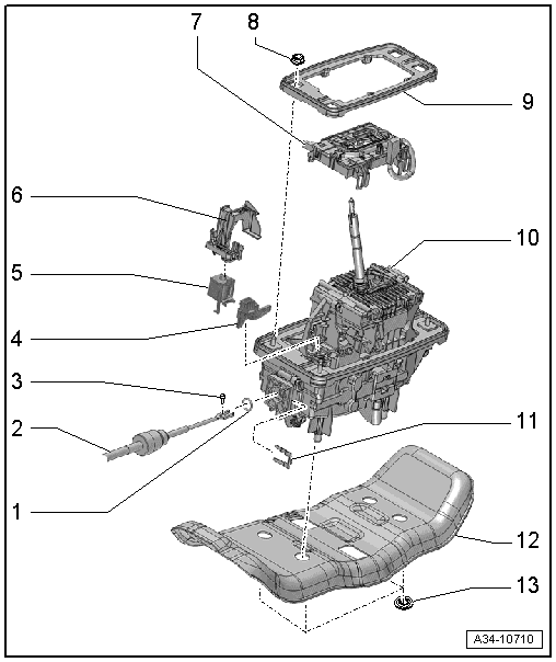
1 - O-Ring
- Replacing
2 - Selector Lever Cable
- Do not bend
- Removing and installing, refer to → Chapter "Overview - Selector Lever Cable".
3 - Bolt
- For selector lever cable adjustment
- Tightening specification -item 3-.
4 - Transmission Park Selector Switch -F305-
- Consists of two micro-switches on the circuit board on the Shift Lock Solenoid - N110-.
- Can only be replaced together with the Shift Lock Solenoid -N110-, refer to → Chapter "Shift Lock Solenoid -N110-, Removing and Installing".
5 - Shift Lock Solenoid -N110-
- Removing and installing, refer to → Chapter "Shift Lock Solenoid -N110-, Removing and Installing".
6 - Cover
- via the Shift Lock Solenoid -N110-
7 - Selector Lever Sensor System Control Module -J587- with Tiptronic Switch -F189-
- Removing and installing, refer to → Chapter "Selector Lever Sensor System Control Module -J587-, Removing and Installing".
8 - Nut
- 8 Nm
- for securing the shift mechanism to the body
- Quantity: 4
9 - Seal
10 - Selector Mechanism Function Unit
- Can only be replaced as a unit
- Removing and installing, refer to → Chapter "Selector Mechanism, Removing and Installing".
- Perform "Guided Functions" using the Vehicle Diagnostic Tester after removing and installing the selector mechanism function unit, refer to → Chapter "Transmission Guided Functions".
11 - Clip
- For selector lever cable
12 - Noise Insulation
- Not installed on all vehicles
- Allocation, refer to the Parts Catalog.
13 - Lock washers
- For the noise insulation
- Quantity: 4
- Replacing
Overview - Selector Lever Cable
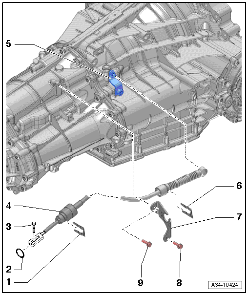
1 - Clip
- For the selector lever cable on the selector mechanism function unit
2 - O-Ring
- Replacing
3 - Bolt
- 13 Nm
- For selector lever cable adjustment
4 - Selector Lever Cable
- Do not bend
- Different versions depending on the vehicle; For the correct allocation, refer to the Parts Catalog.
- Removing and installing, refer to → Chapter "Selector Lever Cable, Removing and Installing".
- The selector lever cable must be replaced if the rubber grommet is damaged.
- Lubricate the ball socket lightly with Polycarbamide Grease -G 052 142 A2- before installing.
- Make sure the rubber grommet on the transmission side is not twisted when installing.
- Adjusting, refer to → Chapter "Selector Lever Cable, Checking and Adjusting".
- Perform "Guided Functions" using the Vehicle Diagnostic Tester after adjusting the selector lever cable, refer to → Chapter "Transmission Guided Functions".
5 - Selector Lever
6 - Clip
- Lock nut 13 Nm depending on the version
- For attaching the selector lever cable to the cable bracket
7 - Cable Mounting Bracket
8 - Bolt
- 8 Nm
9 - Bolt
- 8 Nm
Emergency Release from P
 Note
Note
- The selector lever will not move out of "P" if the battery is disconnected or is discharged. The vehicle cannot be moved or towed.
- The Shift Lock Solenoid -N110- will cancel out the lock when the emergency release is activated.
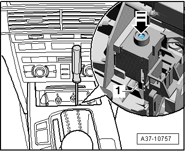
Procedure
Note
The handle on the selector lever is not shown in the illustration. It is not necessary to remove the handle in order to unlock the selector mechanism when it is in "P".
- Pry out the cap -1-.
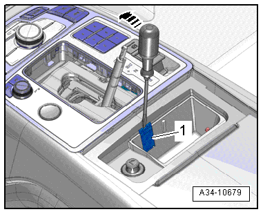
Note
- This unlocks the locking lever -1- when the selector lever is in "P".
- If the cylinder -arrow- on the Shift Lock Solenoid -N110- is covered by insulation or a wire, then move the insulation or the wire to the side.