Audi A6 Typ 4G: Infrared System
Overview - Infrared System
Overview - Infrared System
The infrared system supports the driver while driving in the dark. The infrared system image shows in the instrument cluster a thermal image of the area ahead of the vehicle. The range of view of approximately 300 m extends well beyond the range of the low beam and high beam. Also in absolute darkness living things are visible in the image due to their temperature. The system recognizes pedestrians at a distance range of 13 m to 90 m for the vehicles and marks them in yellow brackets. Additionally the system calculates a warning range using the current speed and yaw rate. If there is a pedestrian in the calculated warning range or is moving towards the range, the system warns before a possible collision with the pedestrian. The color of the marking brackets, that indicate a pedestrian, change to red and a gong sounds.
The infrared system is composed of a Night Vision System Camera -R212- and aNight Vision System Control Module -J853-. The Night Vision System Button -E680- is integrated in the Light Switch -E1-. The Night Vision System Camera -R212- in located in the radiator grille on the outer Audi rings on the left side of the vehicle. The Night Vision System Control Module -J853-is located on the left side of the vehicle in the footwell. The Night Vision System Camera -R212- is a subsystem of the Night Vision System Control Module -J853- and is diagnostic-capable via the Night Vision System Control Module -J853-. If faulty, the Night Vision System Camera -R212- and the Night Vision System Control Module -J853- can be replaced separately. For the Night Vision System Camera -R212- a repair set is offered (for the case of damaged protective window due to stone impact, scratches, sand wear) in which a protective window, a seal, the quick release, two cotton swabs for cleaning the seal area and instructions.
If the protective window is no longer water tight due to damage, the Night Vision System Camera -R212- must be completely replaced. Refer to → Chapter "Night Vision System Camera, Removing and Installing".
The Night Vision System Camera - R212- protective window is cleaned with a spray nozzle. The spray nozzle is paired with the headlamp washer system.
For the infrared system to function correctly a calibration of the Night Vision System Camera -R212- is required.
A new calibration is required when:
- The fault "no or incorrect basic setting/adaptation" is present in the DTC memory.
- The Night Vision System Camera -R212- is removed or exchanged,
- The bumper or radiator grille is removed or exchanged,
- Adjustment work was performed on the rear axle
- Chassis modifications were performed on the vehicle.
After changes that effect the Night Vision System Control Module -J853- (replacing, software update) a new calibration is not required.
 Note
Note
Before calibrating the infrared system read the DTC memory and if necessary perform troubleshooting. The calibration may only be performed with a VW/Audi approved alignment tester. Only use Setting Device -VAS6430- and Setting Device Basic Set -VAS6430/1- with the proper Night Vision Calibration Tool -VAS6430/6- for the calibration of the infrared system
Component Location Overview - Infrared System
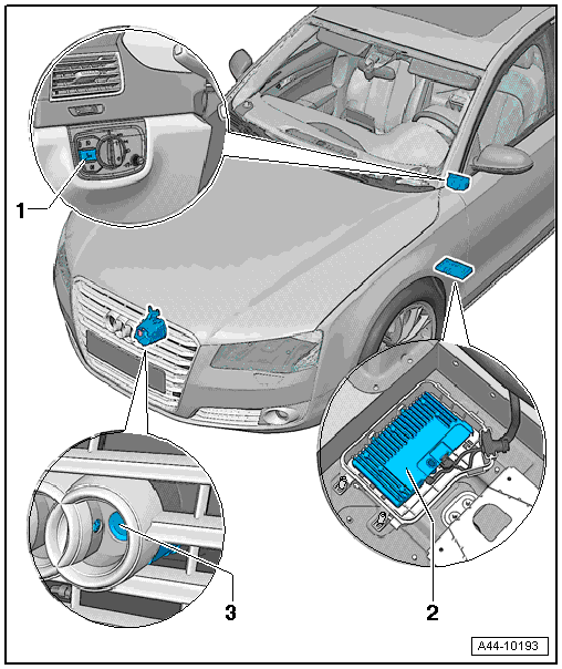
1 - Light Switch -E1- with Night Vision System Button -E680-
- Removing and installing. Refer to → Electrical Equipment; Rep. Gr.96; Controls; Overview - Instrument Panel Controls.
2 - Night Vision System Control Module -J853-
- Component location in front left footwell
- Removing and installing. Refer to → Chapter "Night Vision System Control Module, Removing and Installing"
3 - Night Vision System Camera -R212-
- Removing and installing. Refer to → Chapter "Night Vision System Camera, Removing and Installing"
- Calibration. Refer to → Suspension, Wheels, Steering; Rep. Gr.44; Infrared System; Infrared System, Calibrating.
Overview - Night Vision System Camera -R212-
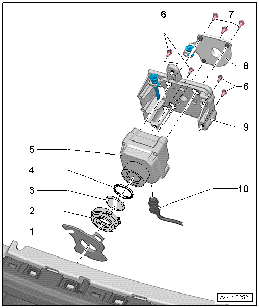
1 - Trim
2 - Cover
- With quick release
3 - Protective Window
- Removing and installing.
Note
If the protective window is no longer water tight due to damage, then the Night Vision System Camera -R212- must be completely replaced.
4 - Seal
- Replace after every removal
5 - Night Vision System Camera -R212-
6 - Bolt
- 6 Nm
- Quantity: 4
7 - Bolt
- 5 Nm
- Quantity: 3
8 - Retaining Plate
9 - Retaining Plate
- With adjusting screw and mount for the spray nozzle
10 - Connector
Night Vision System Camera, Removing and Installing
Special tools and workshop equipment required
- Torque Wrench 1783 - 2-10Nm -VAG1783-
- Hose Clamps - Up To 25mm -3094-
Removing
- Turn off the ignition and all electrical consumers and remove the ignition key.
- Remove the front lock carrier cover. Refer to → Body Exterior; Rep. Gr.50; Lock Carrier; Overview - Lock Carrier.
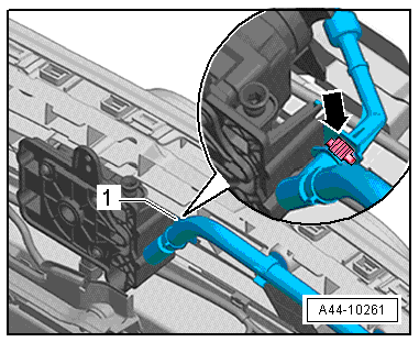
- Release the clamp -arrow-, and remove the washer fluid hose -1-.
- If necessary, clamp off the washer fluid hose at a suitable location using Hose Clamps - Up To 25mm -3094-.
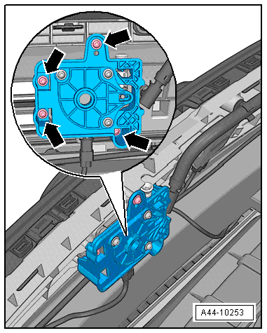
- Remove the bolts -arrows-.
- Remove the Night Vision System Camera -R212- with the retaining plate from the front bumper cover and guide upward. Pay attention that the spray nozzle is not damaged.
- Disconnect the connector from the Night Vision System Camera -R212-.
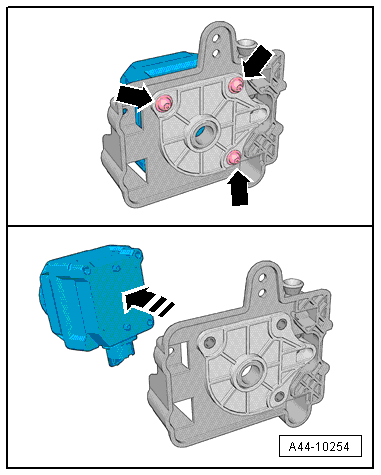
- Remove the bolts -arrows- and remove the Night Vision System Camera -R212- from the retaining plate.
Removing the protective window
- Night Vision System Camera -R212- removed
Note
If the protective window is no longer water tight due to damage, then the Night Vision System Camera -R212- must be completely replaced. Refer to → Chapter "Night Vision System Camera, Removing and Installing".
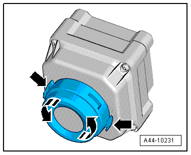
- Remove the trim -item 1-.
- Push the retaining tabs -arrow- together and turn the cover approximately 90º counter-clockwise.
- Remove the cover, protective window and seal from the Night Vision System Camera -R212-.
Note
Depending on the removal the seal may be replaced.
Installing
- Install in reverse order of removal. Note the following:
- Calibrate the night vision system camera. Refer to → Suspension, Wheels, Steering; Rep. Gr.44; Infrared System; Infrared System, Calibrating.
Night Vision System Control Module, Removing and Installing
The Night Vision System Control Module -J853- is located in the front left footwell.
Note
If replacing the control module, select the "Replace Control Module" function on the Vehicle Diagnostic Tester.
Removing
- Turn off the ignition and all electrical consumers and remove the ignition key.
- Loosen the front left seat and with the wires still attached and push rearward. Refer to → Body Interior; Rep. Gr.72; Front Seats; Overview - Front Seat.
- Remove the floor mat.
- Remove the sill panel. Refer to → Body Interior; Rep. Gr.70; Passenger Compartment Trim; Overview - Sill Panel Strip.
- Remove the foot rest. Refer to → Body Interior; Rep. Gr.70; Passenger Compartment Trim; Overview - Foot Rest and Carpet.
- Disengage the carpet and push aside.
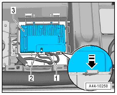
- Release the clips in the direction of the -arrow-.
- Open cover -1-.
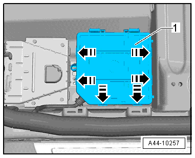
- Push the retaining tab in the direction of the -arrow- and remove the Night Vision System Control Module - J853--3- from the E-box.
- Release connectors -1- and -2- and remove from the Night Vision System Control Module - J853--3-
- First release connector -2- and then -1-.
Installing
Install in reverse order of removal.