Audi A6 Typ 4G: Overview - Peripheral Camera System
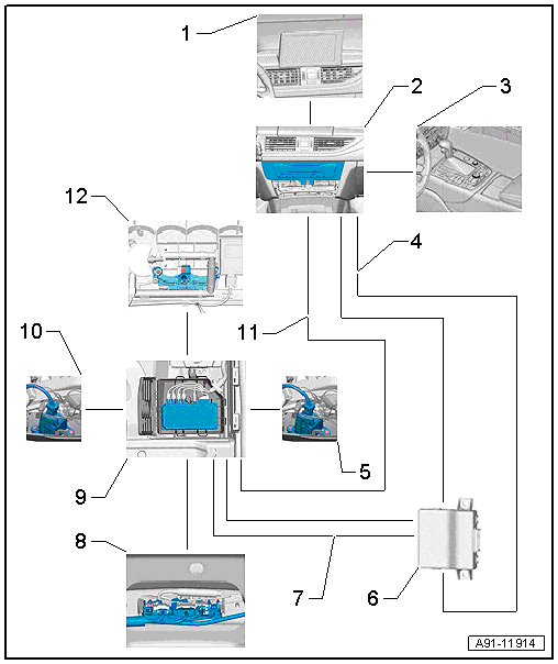
The peripheral camera system (KA6) consists of four cameras. They are located in the radiator grille, in both side exterior mirrors and in the rear lid. The system helps the driver when parking, maneuvering or when driving off-road. The camera images are displayed on the Front Information Display Control Head -J685-.
Camera views that can be selected:
- Bird's-eye view: The images from all 4 cameras (Front Peripheral Camera -R243-/Left Peripheral Camera -R244-/Right Peripheral Camera -R245-/Rear Peripheral Camera -R246-) show the view around the entire vehicle.
- Front camera (front view): the image from the camera inside the front bumper cover (Front Peripheral Camera -R243-) shows the area in front of the vehicle (up to the left and right corners of the bumper).
- Side cameras (side view): the images from the cameras inside the left and right exterior rearview mirrors (Left Peripheral Camera -R244-/Right Peripheral Camera -R245-) show the side areas next to the vehicle.
- Rear camera (rear view): the image from the camera in the rear lid (Rear Peripheral Camera -R246-) shows the area behind the vehicle.
Peripheral camera system components:
- Front Peripheral Camera -R243-
- Left Peripheral Camera -R244-
- Right Peripheral Camera -R245-
- Rear Peripheral Camera -R246-
- Peripheral Camera Control Module -J928-
- Information Electronics Control Module 1 -J794-
Other control modules may be installed as optional equipment.
Installing an additional license is not permitted on vehicles with the peripheral camera system because it will impair the system.
Fault finding is performed via "Guided Fault Finding" on the Vehicle Diagnostic Tester.

1 - Front Information Display Control Head -J685- in center of the instrument panel
2 - Information Electronics Control Module 1 -J794- inside the instrument panel
3 - Multimedia System Control Head -E380- in the center console
4 - MOST Bus
5 - Right Peripheral Camera -R245- inside the right exterior mirror
6 - Data Bus On Board Diagnostic Interface -J533- under the rear bench seat
7 - CAN Bus, INSTRUMENT Cluster
8 - Rear Peripheral Camera -R246- inside the rear lid
9 - Peripheral Camera Control Module -J928- under the right front seat
10 - Left Peripheral Camera -R244- inside the left exterior mirror
11 - CVBS Cable from the Peripheral Camera Control Module -J928-
12 - Front Peripheral Camera -R243- in the center of the front bumper cover
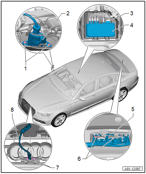
Component Location Overview - Peripheral Camera

1 - Bolt
- 2 Nm
- Quantity: 2
2 - Right Peripheral Camera -R245-/Left Peripheral Camera -R244-
- Removing and installing. Refer to → Body Exterior; Rep. Gr.66; Exterior Rearview Mirror; Overview - Exterior Rearview Mirror.
- Calibrating. Refer to → Chapter "Peripheral Camera System, Calibrating".
3 - E-Box
4 - Peripheral Camera Control Module -J928-
- Connector assignment. Refer to → Wiring diagrams, Troubleshooting & Component locations.
- Removing and installing. Refer to → Chapter "Peripheral Camera Control Module -J928-, Removing and Installing".
- Calibrating. Refer to → Chapter "Peripheral Camera System, Calibrating".
5 - Rear Peripheral Camera -R246-
- Sedan, removing and installing. Refer to → Chapter "Peripheral Camera System, Calibrating".
- Avant, removing and installing. Refer to → Chapter "Rear Peripheral Camera -R246-, Removing and Installing, Avant".
- Calibrating. Refer to → Chapter "Peripheral Camera System, Calibrating".
6 - Nut
- 3 Nm
- Quantity: 2
7 - Bolt
- 3 Nm
- Quantity: 2
8 - Front Peripheral Camera -R243-
- Removing and installing. Refer to → Chapter "Peripheral Camera System, Calibrating".
- Calibrating. Refer to → Chapter "Peripheral Camera System, Calibrating".
No illustration
- Bumper cover end plate screws: 3 Nm

