Audi A6 Typ 4G: Instrument Panel Vent, Removing and Installing
Driver Side Instrument Panel Vent, Removing and Installing
Special tools and workshop equipment required
- Hook Tool -T40207-
Removing
- Remove the instrument cluster gap cover. Refer to → Chapter "Instrument Cluster Gap Cover, Removing and Installing".
- Removing the trim for the instrument panel. Refer to → Chapter "Instrument Panel Decorative Trim, Removing and Installing, Driver Side".
- Remove the instrument panel vent cover. Refer to → Chapter "Instrument Panel Rear Cover, Removing and Installing".
- Remove the Light Switch -E1-. Refer to → Electrical Equipment; Rep. Gr.96; Controls; Overview - Instrument Panel Controls.
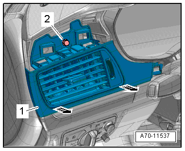
- Remove the bolt -2-.
 Note
Note
The vent has a hole on both sides for attaching the Hook Tool -T40207-.
- Carefully insert the Hook Tool -T40207- between the slats and hook it into the side of the vent.
- Remove the vents -1- on both sides alternating from side to side -arrows-.
- Reach through the opening for the light switch, disconnect the connector and remove the instrument panel vent.
Installing
Install in reverse order of removal. Note the following:
Installation notes, for example tightening specifications, replacing components. Refer to → Chapter "Overview - Instrument Panel".
Passenger Side Instrument Panel Vent, Removing and Installing
Special tools and workshop equipment required
- Hook Tool -T40207-
Removing
Note
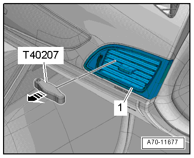
The vent has a hole on both sides for attaching the Hook Tool -T40207-.
- Carefully insert the Hook Tool -T40207- between the slats and hook it into the side of the vent.
- Alternating between the sides, carefully remove the vent -1- from the installation opening -arrow-.
- Disconnect the connector.
Installing
Install in reverse order of removal. Note the following:
Installation notes, for example tightening specifications, replacing components. Refer to → Chapter "Overview - Instrument Panel".
Center Instrument Panel Vent, Removing and Installing
Special tools and workshop equipment required
- Wedge Set -T10383-
Removing
- Remove the instrument cluster gap cover. Refer to → Chapter "Instrument Cluster Gap Cover, Removing and Installing".
- Remove the display unit cover. Refer to → Chapter "Instrument Panel Rear Cover, Removing and Installing".
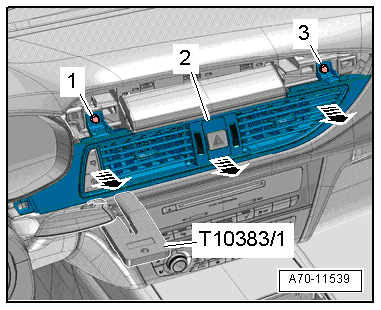
- Remove the bolts -1 and 3-.
- Pry the instrument panel vent -2- out of the instrument panel toward the rear using the Wedge Set -T10383/1--arrows-.
- Disconnect the connectors and remove the instrument panel vent.
Installing
Install in reverse order of removal. Note the following:
Installation notes, for example tightening specifications, replacing components. Refer to → Chapter "Overview - Instrument Panel".
Front Center Defroster Vent, Removing and Installing
Special tools and workshop equipment required
- Wedge Set -T10383-
Removing
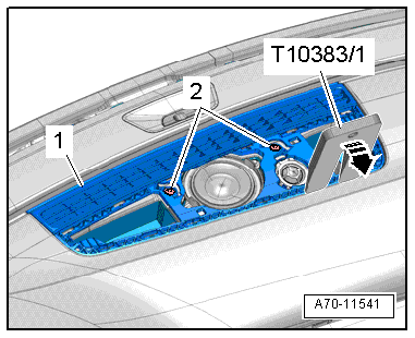
- Remove the center speaker trim. Refer to → Chapter "Center Speaker Trim, Removing and Installing".
- Remove the bolts -2-.
- Pry the defroster vent -1- out of the instrument panel -arrow- at the rear using the Wedge Set -T10383/1- and remove it toward the rear.
Installing
Install in reverse order of removal. Note the following:
Installation notes, for example tightening specifications, replacing components. Refer to → Chapter "Overview - Instrument Panel".
Side Defroster Vent, Removing and Installing
Special tools and workshop equipment required
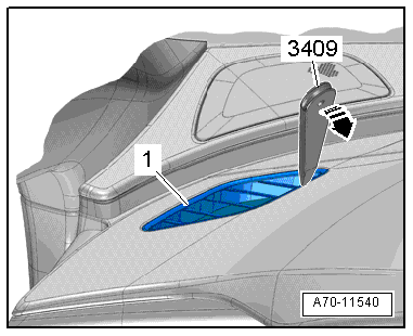
- Trim Removal Wedge -3409-
Removing
- Remove the defroster vent -1- from the instrument panel -arrow- using a Trim Removal Wedge -3409-.
Installing
Install in reverse order of removal. Note the following:
Installation notes, for example tightening specifications, replacing components. Refer to → Chapter "Overview - Instrument Panel".