Audi A6 Typ 4G: Light Switch -E1-, Removing and Installing
Removing
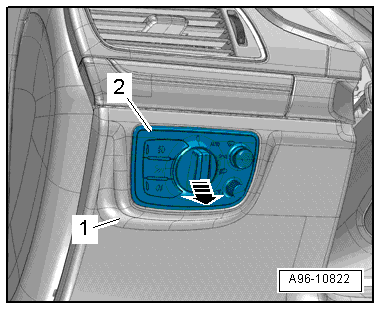
- Turn the light switch to position "0".
- Remove the instrument panel side cover. Refer to → Body Interior; Rep. Gr.70; Instrument Panel; Instrument Panel Side Cover, Removing and Installing.
- Reach through the opening between the instrument panel and fuse panel C and push the light switch -2- out of the instrument panel cover -1- on the driver side in direction of -arrow-.
- Disconnect the connector.
Installing
Install in reverse order of removal. Note the following:
- Push the switch into the switch housing until it clicks into place.
Instrument Panel and Switch Illumination Dimmer Switch -E20-, Removing and Installing
The Instrument Panel And Switch Illumination Dimmer Switch -E20- is seated in a shared housing with the Light Switch -E1- and cannot be replaced separately if faulty.
- Replacing the Light Switch -E1-. Refer to → Chapter "Light Switch -E1-, Removing and Installing".
Headlamp Range Control Adjuster -E102-, Removing and Installing
Removing
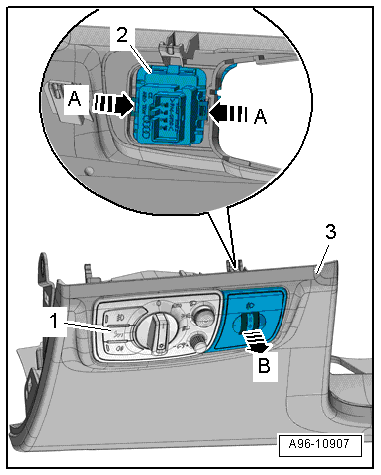
- Remove the light switch -1-. Refer to → Chapter "Light Switch -E1-, Removing and Installing".
- Remove the headlamp range control adjuster -2- from the driver side instrument panel cover in direction of -arrow B-. The tabs are opened when doing this in direction of -arrows A-.
 Note
Note
If the headlamp range control adjuster cannot be removed as described, then the driver side instrument panel cover must be removed. Refer to → Body Interior; Rep. Gr.68; Storage Compartments and Covers; Driver Side Instrument Panel Cover, Removing and Installing.
Installing
Install in reverse order of removal.
Rear Fog Lamp Button -E314-/Fog Lamp Button -E315-/Night Vision System Button -E680-, Removing and Installing
The Rear Fog Lamp Button -E314-, the Fog Lamp Button -E315- and the Night Vision System Button -E680- are contained in a shared housing inside the Light Switch -E1- and cannot be replaced individually if one is faulty.
- Replacing the Light Switch -E1-. Refer to → Chapter "Light Switch -E1-, Removing and Installing".
Steering Column Adjustment Switch -E167- and Steering Wheel Heating Button -E522-, Removing and Installing
Removing
- Remove the lower trim for the steering column switch module. Refer to → Body Interior; Rep. Gr.68; Storage Compartments and Covers; Overview - Steering Column Trim Panel.
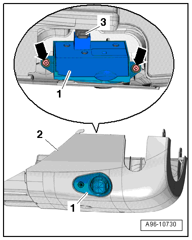
- Remove the bolts -arrows-.
- Remove the Steering Column Adjustment Switch -E167--item 1- upward from the lower trim panel -2-.
Note
Disregard -item 3-.
Installing
Install in reverse order of removal.
Front Display Open/Close Button -E462-/Display Unit Button -E506-, Removing and Installing
Removing
- Remove the center instrument vent. Refer to → Body Interior; Rep. Gr.70; Instrument Panel; Instrument Panel Vent, Removing and Installing.
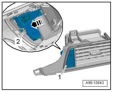
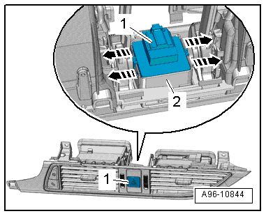
- Remove the switch unit -1- from the mount -2- in direction of -arrow-.
- Remove the switch unit.
Installing
Install in reverse order of removal.
Instrument Panel Button, Removing and Installing
Special tools and workshop equipment required
- Radio Removal Tool -T10057-
Note
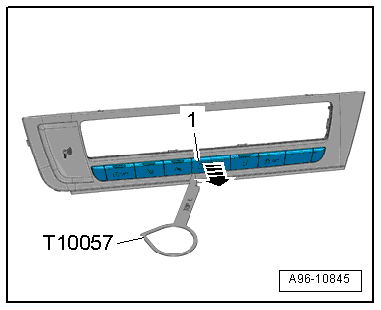
The ASR/ESP Button -E256-/Parking Aid Button -E266-/Parallel Parking Assistance Button -E581-/Start/Stop Mode Button -E693-/Front Passenger Airbag -Disabled- Indicator Lamp -K145- are a single component.
Removing
- Trim for the Information Electronics Control Module 1 -J794-. Refer to → Body Interior; Rep. Gr.70; Instrument Panel; Overview - Instrument Panel.
- Install the Radio Removal Tool -T10057- into the opening on the left and right side as illustrated and pry off the cover -1- for the Front Passenger Airbag -Disabled- Indicator Lamp -K145- in direction of -arrow-.
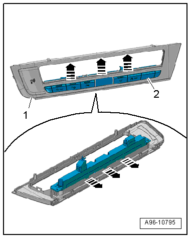
- Open the tabs in direction of -arrows- and remove the switch unit -2- from the trim -1- on the Information Electronics Control Module 1 -J794- toward the rear.
Installing
Install in reverse order of removal. Note the following:
- Install the switch until it clicks into place.
- Install the Front Passenger Airbag -Disabled- Indicator Lamp -K145- cover.
Emergency Flasher Button -E229-, Removing and Installing
Removing
- Remove the center instrument vent. Refer to → Body Interior; Rep. Gr.70; Instrument Panel; Instrument Panel Vent, Removing and Installing.
- Release the tabs -arrows-.
- Remove the emergency flasher button -1- toward the rear out of the mount -2-.
Installing
Install in reverse order of removal. Note the following:
- Install the emergency flasher button until it clicks into place.
Left/Right Seat Heating Button -E653-/-E654-, Removing and Installing
The seat heater buttons are integrated in Climatronic Control Module -J255- (also called "control head"). They cannot be replaced separately.
- Replacing the Climatronic Control Module -J255-. Refer to → Heating, Ventilation, and Air Conditioning; Rep. Gr.87; Display and Control Head; Display and Control Head, Removing and Installing.
