Audi A6 Typ 4G: Lock Carrier Trim Panel, Removing and Installing
Lock Carrier Trim Panel, Removing and Installing, Sedan
Special tools and workshop equipment required
- Pry Lever -80-200-
- Omega Clip Tool -T40280-
Removing
- A6 hybrid: remove the luggage compartment floor covering. Refer to → Chapter "Luggage Compartment Floor, Removing and Installing, A6 Hybrid".
- Fold the luggage compartment floor covering forward.
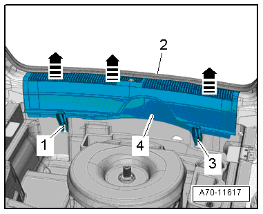
- Remove the rear lid seal -2- near the rear lid end panel trim panel.
- Unclip the rear lid end trim panel -4- upward vertically using the Pry Lever -80-200- in direction of -arrows- and remove.
 Note
Note
A lot of force is be needed to remove the rear lid end panel trim panel from the rear lid end piece.
Installing
Install in reverse order of removal. Note the following:
- The tabs must fit into the pins -1 and 3-.
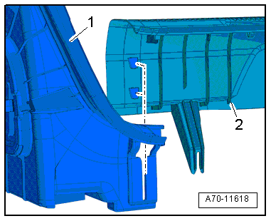
- The rear lid end panel trim panel -2- must engage in the luggage compartment side trim panel -1-.
- Fold the rear lid seal over the rear lid end panel trim panel.
Installation notes, for example tightening specifications, replacing components. Refer to → Chapter "Overview - Lock Carrier Trim Panel, Sedan".
Lock Carrier Trim Panel, Removing and Installing, Avant
Special tools and workshop equipment required
- Pry Lever -80-200-
- Omega Clip Tool -T40280-
Removing
- Lift the luggage compartment floor covering at the handle and fold it forward.
- Remove the replacement part and the spare wheel well cover.
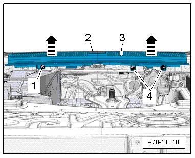
- Remove the bolts -1 and 4-.
- Remove the rear lid seal -2- near the rear lid end panel trim panel.
- Unclip the rear lid end trim panel -3- upward vertically using the Pry Lever -80-200--arrows-.
Installing
Install in reverse order of removal. Note the following:
Installation notes, for example tightening specifications, replacing components. Refer to → Chapter "Overview - Lock Carrier Trim Panel, Avant".
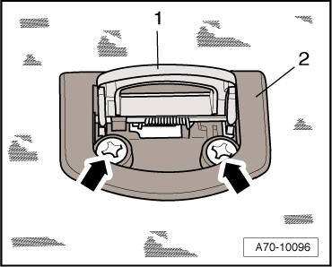
Emergency Triangle Bracket, Removing and Installing
Removing
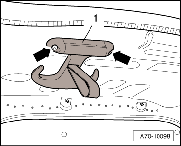
- Remove the warning triangle from the bracket by pressing the release.
- Release retaining tabs using a screwdriver in direction of -arrows- and remove warning triangle bracket -1-.
Installing
Install in reverse order of removal. Note the following:
Installation notes, for example tightening specifications, replacing components. Refer to → Chapter "Overview - Lower Rear Lid Trim Panel, Sedan".
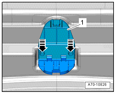
Tie Down, Removing and Installing
Removing
- Fold the tie-downs -1- upward.
- Remove the bolts -arrows- and the mount for the tie down -2-.
Installing
Install in reverse order of removal. Note the following:
Installation notes, for example tightening specifications, replacing components. Refer to → Chapter "Overview - Luggage Compartment Side Trim Panel".
Luggage Compartment Floor Covering Bracket, Removing and Installing
 WARNING
The engine could start unexpectedly.
For general work performed on the high voltage system the ignition must be switched off and the key must be kept outside of the vehicle interior.
DANGER!
High voltage components have hazardous voltage.
Note the following when working near high voltage components and high voltage cables:
- Cutting, deformed, and sharp edged tools or heat sources such as welding, solder, hot air and thermal glue are forbidden.
- Visually inspect the work area before working on high voltage components.
- Perform a visual inspection of the Electric Drive Power and Control Electronics -JX1-, the Electro-Drive Drive Motor -V141-, the Electrical A/C Compressor -V470- and the high voltage lines when working in the engine compartment.
- Visually inspect the high voltage cables and the covers when working on the underbody.
- Visually inspect the high voltage cables, the electronics and the High Voltage System Maintenance Connector -TW -, when working in the luggage compartment.
- Visually inspect all potential equalization cables.
Observe the following when performing the visual inspection:
- None of the components appear to have any external damage.
- The high voltage cable insulation and the potential equalization cable insulation are not damaged.
- The high voltage cables must not have any unusual deformations.
- Each high voltage component must be marked with a red warning label.
Removing
- Remove the luggage compartment liner. Refer to → Chapter "Luggage Compartment Floor, Removing and Installing, A6 Hybrid".
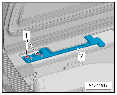
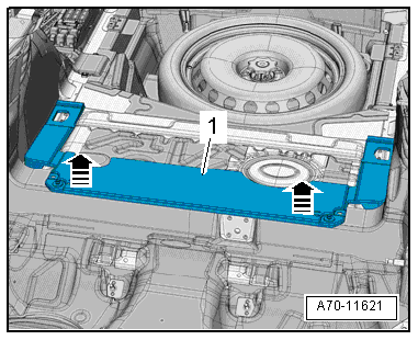
Rear Bracket
- Remove the bolts -1-.
- Remove the mount -2-.
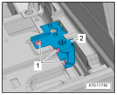
Front Bracket
- Remove the cover from the traction battery.
- Remove the bolts -1-.
- Remove the bracket -2- for the traction battery cover.
Installing
Install in reverse order of removal. Note the following:
Installation notes, for example tightening specifications, replacing components. Refer to → Chapter "Overview - Luggage Compartment Floor, A6 Hybrid".
Rear Panel Sill Frame, Removing and Installing
Special tools and workshop equipment required
- Trim Removal Wedge -3409-
Removing
- Remove the luggage compartment side trim. Refer to → Chapter "Luggage Compartment Side Trim Panel, Removing and Installing".
- Unclip the rear panel sill frame -1- at the front using the Trim Removal Wedge -3409--arrows- and remove it.
Installing
Install in reverse order of removal. Note the following:
Installation notes, for example tightening specifications, replacing components. Refer to → Chapter "Overview - Luggage Compartment Floor, Sedan".
Coat Hooks, Removing and Installing
Removing
- Remove screws -arrows-, remove retaining hooks -1-.
Installing
Install in reverse order of removal. Note the following:
Installation notes, for example tightening specifications, replacing components. Refer to → Chapter "Overview - Luggage Compartment Floor, Sedan".
Rear Luggage Compartment Floor Handle, Removing and Installing
Special tools and workshop equipment required
- Pry Lever -80-200-
Removing
- Remove the luggage compartment liner. Refer to → Chapter "Luggage Compartment Floor Panel, Removing and Installing".
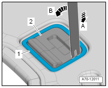
- Release the mounting bracket -1- from the underside of the luggage compartment floor.
- To do this position the Pry Lever -80-200- in direction of -arrow A-, and release the mounting bracket in direction of -arrow B-.
- Release the mounting bracket, and remove the luggage compartment floor panel handle -2-.
Installing
Install in reverse order of removal. Note the following:
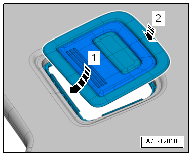
- Position the mounting bracket -arrow- from below on the cut-out in the luggage compartment floor and hold.
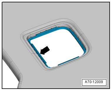
- Push the luggage compartment handle opposite of direction of travel in the mounting bracket in direction of -arrow 1- and lock downward in direction of -arrow 2-.
Installation notes, for example tightening specifications, replacing components. Refer to → Chapter "Overview - Luggage Compartment Floor".