Audi A6 Typ 4G: Tires, Rolling Noises
Tires, Rolling Noises, General Information
Rolling noise perceived by the human ear is caused by vibrations transmitted from the noise source to the ear via the air.
Here we are interested in noises created by certain characteristics of the tires as well as the effects of rolling (noise source).
The cause for the noise generation depends primarily on the combination of road surface and tire.
The surface structure and material of the road surface also have a strong influence on the rolling noise. For example, the noise level on a wet road is substantially higher than on a dry road.
The design of the tread has a great influence on the noise generation. Tires with cross grooves at an angle of 90º are louder than tires with grooves running diagonally.
Small tread blocks are unstable. Due to strong deformation, the air is excited by the rolling tires. Air vibrations occur, which will generate noises.
Wider tires are louder. They require more tread grooves for water displacement. Air is displaced by these tread grooves while rolling, which also cause air vibrations.
Other effects which also have an influence on noise generation:
- Tire vibration is the main cause of rolling noise. The noise is generated by the excitation of the air column in the grooves.
- Air pumping is the compression and expansion of air as the contact patch comes in contact with the road surface and the tread blocks are deformed.
Heel and Toe Wear
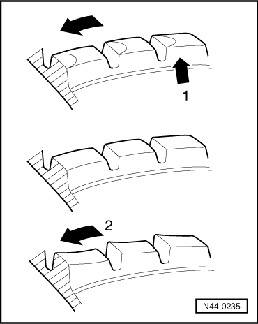
Heel-and-toe wear is step-like wear of individual tread blocks (see illustration), due to which an increased rolling noise can develop. The heel-and-toe wear is caused by the uneven distortion of the tread blocks in the contact patch. Heel-and-toe wear appears in more extreme forms on non-tractive wheels than on tractive wheels.
New tires have a stronger tendency to heel-and-toe wear, because the high tread blocks have greater elasticity. As tread depth decreases, the rigidity of the tread blocks increases and the tendency to heel-and-toe wear decreases.
How does the heel-and-toe wear look?
The tread blocks are higher in the front than back when viewed in running direction, see illustration. Extreme heel-and-toe wear may lead to customer complaints about noise.
Increased heel-and-toe wear occurs with:
- Toe values too great
- Incorrect air pressure
- Deep, open treads
- Tires which are not mounted on the tractive axle
- Extreme cornering
1 - Tread block, heavy wear at front of tread block
2 - Running direction
Non-directional tires:
When heel-and-toe wear occurs, the direction of travel of the tire must be reversed. If increased heel-and-toe wear and rolling noise develop, the tires should be rotated diagonally. This leads to a reduction of heel-and-toe wear. On vehicles with front wheel drive, this effect is increased by increased wear on front axle. The rolling noise is somewhat louder immediately after rotating the wheels, but the normal noise level will be reached after traveling approximately 500 to 1,000 km (310 to 621 miles).
Directional tires:
In the event of increased heel-and-toe wear of the tires on the rear axle - most common with front-wheel drive - rotate the wheels from back to front. In the event of increased heel-and-toe wear on the outer edges on one axle, reverse both tires on their rims. Then the left wheel must be mounted on the right side and the right wheel on the left side.
Heel-and-toe wear is a normal wear pattern and on non-directional tires, it is reduced by diagonal tire rotation after approximately 500 to 1,000 km (310 to 621 miles).
The previous repair attempt should be briefly described on the complaint report.
Modern tires are designed for maximum driver safety even in wet conditions. Heel-and-toe wear is promoted by the open tread configuration in the tire flanks and the soft tread compound that is necessary to ensure this safety.
Heel-and-toe wear is not a fault in the warranty sense but rather is a completely normal wear pattern.
Wear Spots
Wear spots are caused by a hard stop with locked wheels whereby the rubber compound is abraded from the contact patch.
When the tires slide across the road surface, frictional heat is generated which reduces the abrasion resistance on the tread compound.
Even the most abrasion-resistant tread compound cannot prevent wear spots which can occur during extreme braking.
Even ABS cannot completely prevent brief locking and the resulting slightly flat spots.
The degree of abrasion is primarily dependent on the vehicle speed, road surface and tire load. For clarification see the following examples.
If a vehicle with locked front wheels is decelerated until it comes to a stop, the abrasion of rubber on the post card sized contact patch is approximately:
- From 57 km/h (35 mph) = 23.8 m (78 ft) braking distance, up to 2.0 mm
- From 75 km/h (47 mph) = 41.8 m (137 ft) braking distance, up to 3.3 mm
- From 92 km/h (57 mph) = 71.6 m (235 ft) braking distance, up to 4.8 mm
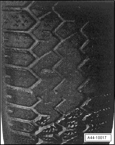
Wear spots in tread.
Tires with this type of damage cannot be used and must be replaced.
Warranty is not possible for tire damage due to braking wear spots or other driving errors (SA 13 - Untrue/imbalance; SA 20 - Driving noise).