Audi A6 Typ 4G: Instrument Cluster Frame, Removing and Installing
Special tools and workshop equipment required
- Trim Removal Wedge -3409-
Removing
- Move the steering wheel as far down as possible.
- Remove the instrument cluster gap cover. Refer to → Chapter "Instrument Cluster Gap Cover, Removing and Installing".
- Remove the instrument panel vent on the driver side. Refer to → Chapter "Driver Side Instrument Panel Vent, Removing and Installing".
- Remove the center instrument panel vent. Refer to → Chapter "Center Instrument Panel Vent, Removing and Installing".
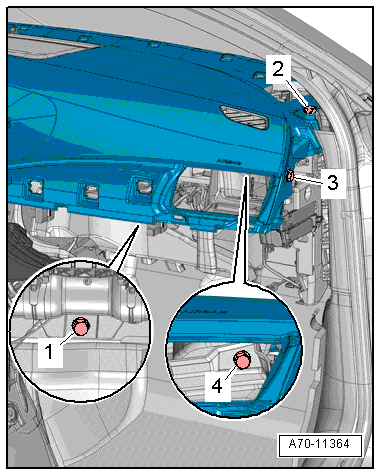
- Remove the bolts -1 and 3-.
- Carefully unclip the frame -2- from the instrument cluster using the Trim Removal Wedge -3409--arrow- and remove it.
Installing
Install in reverse order of removal. Note the following:
Installation notes, for example tightening specifications, replacing components. Refer to → Chapter "Overview - Instrument Panel".
Instrument Panel, Removing and Installing
Removing
- Move the steering wheel as far down as possible.
- Move the front seat all the way back and tilt backrests 45º.
 WARNING
- Follow all Safety Precautions when working with pyrotechnic components. Refer to → Chapter "Pyrotechnic Components Safety Precautions".
- Follow the allocation of the airbag to the instrument panel. Refer to the Parts Catalog.
- Disconnect the battery Ground (GND) cable with the ignition turned on. Refer to → Electrical Equipment; Rep. Gr.27; Battery; Battery, Disconnecting and Connecting.
- Remove the driver side airbag. Refer to → Chapter "Airbag Unit with Igniter, Removing and Installing".
- Remove the steering wheel. Refer to → Suspension, Wheels, Steering; Rep. Gr.48; Steering Wheel; Steering Wheel, Removing and Installing.
- Remove the instrument panel cover on the driver side. Refer to → Chapter "Driver Side Instrument Panel Cover, Removing and Installing".
- Remove the glove compartment. Refer to → Chapter "Glove Compartment, Removing and Installing".
- Remove the instrument panel vent on the driver side. Refer to → Chapter "Driver Side Instrument Panel Vent, Removing and Installing".
- Remove front passenger side instrument panel vent. Refer to → Chapter "Passenger Side Instrument Panel Vent, Removing and Installing".
- Remove the center instrument panel vent. Refer to → Chapter "Center Instrument Panel Vent, Removing and Installing".
- Remove the instrument cluster. Refer to → Chapter "Instrument Cluster Frame, Removing and Installing".
- Remove the instrument cluster. Refer to → Electrical Equipment; Rep. Gr.90; Instrument Cluster; Overview - Instrument Cluster.
- Remove the Front Information Display Control Head -J685-. Refer to → Communication; Rep. Gr.91; Infotainment System; Infotainment System Display, Removing and Installing.
- Remove the Climatronic Control Module -J255-. Refer to → Heating, Ventilation and Air Conditioning; Rep. Gr.87; Display and Control Head; Display and Control Head, Removing and Installing.
- Remove the Information Electronics Control Module 1 -J794-. Refer to → Communication; Rep. Gr.91; Infotainment System; Information Electronics Control Module 1J794, Removing and Installing.
- Remove the upper instrument panel cover. Refer to → Chapter "Instrument Panel Upper Cover, Removing and Installing".
- Remove the instrument panel center speaker. Refer to → Communication; Rep. Gr.91; Sound System; Center Speaker, Removing and Installing.
- Remove the center console. Refer to → Chapter "Center Console, Removing and Installing".
- Country-specific with knee airbag: remove the knee airbag mount. Refer to → Chapter "Knee Airbag Bracket, Removing and Installing".
WARNING
Before handling pyrotechnic components (for example, disconnecting the connector), the person handling it must "discharge static electricity". This can be done by touching the door striker, for example.
- Disconnect the connectors for the front passenger airbag. Refer to → Chapter "Front Passenger Airbag Unit with Igniter, Removing and Installing".
- Remove the Anti-Theft Immobilizer Reader Coil -D2-. Refer to → Electrical Equipment; Rep. Gr.96; Immobilizer; Anti-Theft Immobilizer Reader Coil, Removing and Installing.
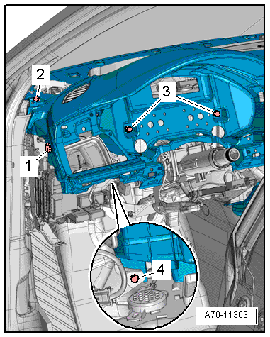
- Vehicles with windshield projection head up display: remove the screws -1, 2 and 5- and the Windshield Projection Head Up Display Control Module -J898- loose with the instrument panel.
- To do this, slightly lift the control module -3- out and disconnect the connector -4-.
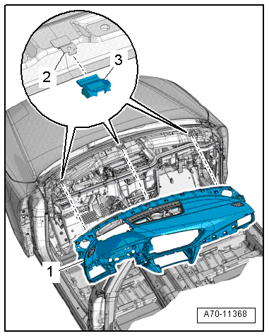
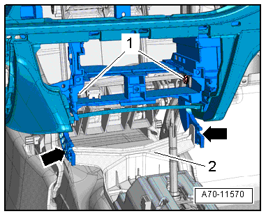
- Remove bolts -1 through 4- for instrument panel on the driver side instrument panel central tube.
- Remove bolts -1 through 4- for instrument panel on the front passenger side instrument panel central tube.
- Remove the instrument panel bolts -1- on the center of the instrument panel central tube.
 Note
Note
Two technicians are needed to remove the instrument panel.
- Disengage the bottom of the instrument panel from the bracket -2--arrows- at the same time.
- Disconnect the connectors and free up the wiring harnesses.
- Carefully pull the instrument panel back from the instrument panel central tube.
- Remove the instrument panel from the vehicle interior and lay it on a soft surface.
Installing
Install in reverse order of removal. Note the following:
WARNING
Follow the allocation of the airbag to the instrument panel. Refer to the Parts Catalog.
- Set the instrument panel in place and guide the electrical harness connectors for Sunlight Photo Sensor -G107- and speaker through the openings in the instrument panel.
- Vehicles with windshield projection head up display: mount the windshield projection head up display control module -3- and the instrument panel.
- Connect the connector -4- and tighten the screws -1, 2 and 5-. Refer to → Electrical Equipment; Rep. Gr.90; Instrument Cluster; Overview - Windshield Projection Head Up Display.
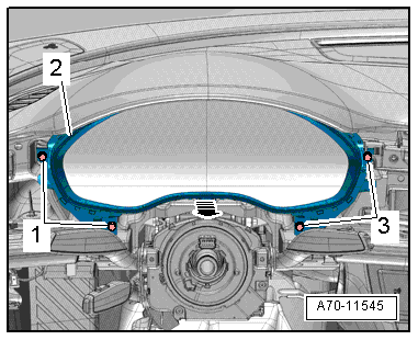
- Check if there is a rubber buffer -3- on the instrument panel mount -2- on the lower windshield frame.
- When sliding on the instrument panel -1-, make sure the instrument panel mounts engage in the box-shaped profiles on the bottom side of the instrument panel.
WARNING
- Follow all Safety Precautions when working with pyrotechnic components. Refer to → Chapter "Pyrotechnic Components Safety Precautions".
- Before handling pyrotechnic components (for example, connecting the connector), the person handling it must "discharge static electricity". This can be done by touching the door striker, for example.
Note
Make sure the connectors are installed correctly and are secure.
- Align the instrument panel and tighten the bolts.
WARNING
Ignition must be on when connecting battery. If pyrotechnic components (for example, airbag, belt tensioner) are not repaired correctly, they may deploy unintentionally after connecting battery. There must not be anyone inside the vehicle when connecting the battery.
DANGER!
When working on vehicles with the ignition already switched on or that are ready to drive there is a danger of the engine starting unexpectedly and of being poisoned by gas in enclosed areas. Risk of body parts and/or clothing being clamped or pulled.
Perform the following before switching on the ignition:
- Move the selector lever into P.
- Activate the parking brake
- Turn off the ignition.
- Open the hood
- Connect the charger, such as the Battery Charger -VAS5095A- to the jump start of the 12V vehicle electrical system.
- Turn on the ignition.
- Connect the battery Ground (GND) cable with the ignition turned on. Refer to → Electrical Equipment; Rep. Gr.27; Battery; Battery, Disconnecting and Connecting.
Note
If the Airbag Indicator Lamp -K75- indicates a fault, check the Diagnostic Trouble Code (DTC) memory, erase it and check it again. Refer to Vehicle Diagnostic Tester.
Installation notes, for example tightening specifications, replacing components. Refer to → Chapter "Overview - Instrument Panel".