Audi A6 Typ 4G: Overview - Radio
MMI Radio, 8DN
8DN -MMI Radio, RMC Radio basic
- Information Electronics Control Module 1 -J794- in the instrument panel holds the CD player
- Radio -R- integrated in the Information Electronics Control Module 1 -J794-
- Front Information Display Control Head -J685-, display in center of the instrument panel
- Multimedia System Control Head -E380- in the center console, QW1
- Sound systems: basic/Standard (8RX/9VD)
Optional
- CD Changer -R41- in glove compartment, 7A2
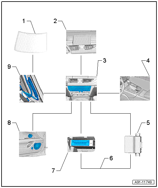
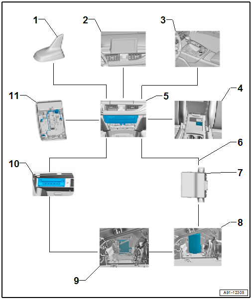
1 - Antenna -R11-/Radio Antenna 2 -R93- in the rear window
2 - Front Information Display Control Head -J685-, display in center of the instrument panel
3 - Information Electronics Control Module 1 -J794- inside the instrument panel
4 - Multimedia System Control Head -E380- in the center console
5 - Data Bus On Board Diagnostic Interface -J533- under the rear bench seat
6 - MOST Bus
7 - CD Changer -R41- in glove compartment
8 - Sound systems: Basic/Standard
9 - Antenna amplifier on the D-pillars/on the rear lid
Fault finding is performed via "Guided Fault Finding" on the Vehicle Diagnostic Tester.
Notes on MOST Bus
The optical Data bus "MOST Bus" is used in addition to the CAN Bus.
A fiber-optic cable is used. Fiber optic cables are routed inside corrugated tubes for protection.
Replace complete fiber-optic cable if possible.
The front surface of the connectors must not be dirty.
If disconnecting the connectors: Attach Fiber-Optic Repair Set - Connector Protective Caps -VAS6223/9-.
When installing fiber-optic cables, make sure not to go below the minimum bending radius of 25 mm. Do not crush or kink fiber-optic cables.
Repairing fiber-optic cables. Refer to → Electrical Equipment General Information; Rep. Gr.97; Wiring Harness and Connector Repairs; Fiber-Optic Cables, Repairing.
MMI Radio plus, 8DP
- Information Electronics Control Module 1 -J794- in the instrument panel holds the CD player/SD card reader
- The Radio -R- is integrated in the Information Electronics Control Module 1 -J794-
- Front Information Display Control Head -J685-, display in center of the instrument panel
- Multimedia System Control Head -E380- in the center console, QW1
- External Audio Source Connection -R199- (AUX IN jack) in the center console storage compartment
- Sound System: Standard, 9VD
Optional
- Digital Radio -R147- integrated in the Information Electronics Control Module 1 -J794-, only ER1/ER2 and QV3
- Radio System, Satellite -R146- integrated in the Information Electronics Control Module 1 -J794-, only ER3 and QV3
- CD Changer -R41- in glove compartment, 7A2
- External Audio Source Connection -R199- in the center console storage compartment, UF7
- Sound System: BOSE, 8RY
- Digital Sound System Control Module -J525- in the luggage compartment on the left rear side
- Cell phone preparation, 9ZF
- Bluetooth Hands-Free Calling, 9ZX
- Voice recognition system, QH1
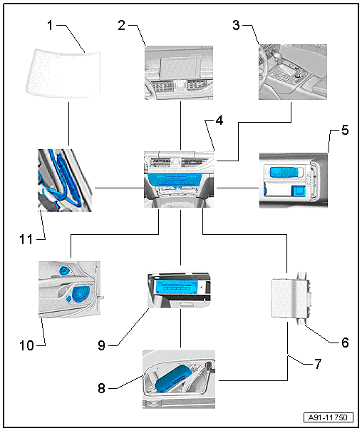
1 - Antenna -R11-/Radio Antenna 2 -R93- in the rear window
2 - Front Information Display Control Head -J685-, display in center of the instrument panel
3 - Multimedia System Control Head -E380- in the center console
4 - Information Electronics Control Module 1 -J794- inside the instrument panel
5 - External Audio Source Connection -R199- in the center console storage compartment
6 - Data Bus On Board Diagnostic Interface -J533- under the rear bench seat
7 - MOST Bus
8 - Digital Sound System Control Module -J525- in luggage compartment on left rear side
9 - CD Changer -R41- in glove compartment
10 - Standard/BOSE Sound Systems
11 - Antenna amplifier on the D-pillars/on the rear lid
Fault finding is performed via "Guided Fault Finding" on the Vehicle Diagnostic Tester.
Notes on MOST Bus
The optical Data bus "MOST Bus" is used in addition to the CAN Bus.
A fiber-optic cable is used. Fiber optic cables are routed inside corrugated tubes for protection.
Replace complete fiber-optic cable if possible.
The front surface of the connectors must not be dirty.
If disconnecting the connectors: Attach Fiber-Optic Repair Set - Connector Protective Caps -VAS6223/9-.
When installing fiber-optic cables, make sure not to go below the minimum bending radius of 25 mm. Do not crush or kink fiber-optic cables.
Repairing fiber-optic cables. Refer to → Electrical Equipment General Information; Rep. Gr.97; Wiring Harness and Connector Repairs; Fiber-Optic Cables, Repairing.
MMI Navigation plus, 8YQ, through MY 2014
- Information Electronics Control Module 1 -J794- with CD player/DVD Player/SD card reader/navigation system integrated in the instrument panel
- Internal hard drive memory (HDD) for storing navigation data and MP3 files
- Front Information Display Control Head -J685-, display in center of the instrument panel
- Multimedia System Control Head -E380- in the center console, QW1
- DVD Changer -R161- in the glove compartment, 6G0
- External Audio Source Connection -R199- in the center console, UF7
- Digital Sound System Control Module -J525- in the luggage compartment on the left rear side
- Sound systems: Standard/BOSE/Bang & Olufsen, 9VD/8RY/8RF
- Radio -R- in the luggage compartment on the left rear side
Optional
- Digital Radio -R147- integrated in the Radio -R-, only ER1/ER2 and QV3
- Satellite Radio -R146- integrated in the Radio -R-, only ER3 and QV8
- TV Tuner -R78- in the luggage compartment on the left rear side, QU6/QU7
- Bluetooth Hands-Free Calling, 9ZX
- Bluetooth car phone, 9ZW
- Voice recognition system, QH1
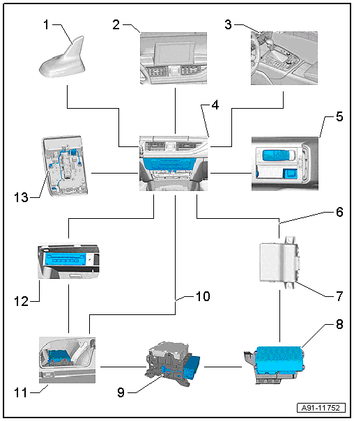
1 - Roof Antenna -R216-
2 - Front Information Display Control Head -J685-, display in center of the instrument panel
3 - Multimedia System Control Head -E380- in the center console
4 - Information Electronics Control Module 1 -J794- inside the instrument panel
5 - External Audio Source Connection -R199- in the center console storage compartment
6 - MOST Bus
7 - Data Bus On Board Diagnostic Interface -J533- under the rear bench seat
8 - Digital Sound System Control Module -J525- in luggage compartment on left rear side
9 - Radio -R- in the luggage compartment on the left rear side
10 - CVBS Cable
11 - TV Tuner -R78- on the left side of the luggage compartment in the rear
12 - DVD Changer -R161- in the glove compartment
13 - Left Front Microphone -R140-, Microphone Unit in Front Roof Module -R164- in the Front Interior Lamp -W1-
The MOST Bus performs the system data exchange in the MMI.
The connection to the other Data bus systems in the vehicle are provided by the Data Bus On Board Diagnostic Interface -J533-.
Fault finding is performed via "Guided Fault Finding" on the Vehicle Diagnostic Tester.
Notes on MOST Bus
The optical Data bus "MOST Bus" is used in addition to the CAN Bus.
A fiber-optic cable is used. Fiber optic cables are routed inside corrugated tubes for protection.
Replace complete fiber-optic cable if possible.
The front surface of the connectors must not be dirty.
If disconnecting the connectors: Attach Fiber-Optic Repair Set - Connector Protective Caps -VAS6223/9-.
When installing fiber-optic cables, make sure not to go below the minimum bending radius of 25 mm. Do not crush or kink fiber-optic cables.
Repairing fiber-optic cables. Refer to → Electrical Equipment General Information; Rep. Gr.97; Wiring Harness and Connector Repairs; Fiber-Optic Cables, Repairing.
MMI Navigation plus, I8H, from MY 2015
- Information Electronics Control Module 1 -J794- with CD player/DVD Player/SD card reader/navigation system integrated in the instrument panel
- Internal hard drive memory (HDD) for storing navigation data and MP3 files
- Front Information Display Control Head -J685-, display in center of the instrument panel
- Multimedia System Control Head -E380- in the center console, QW1
- DVD Changer -R161- in the glove compartment, 6G2
- External Audio Source Connection -R199- in the Center Console Storage Compartment
- Digital Sound System Control Module -J525- in the luggage compartment on the left rear side
- Sound systems: Standard/BOSE/Bang & Olufsen, 9VD/8RY/8RF
- The Radio -R- is integrated in the Information Electronics Control Module 1 -J794-
Optional
- TV Tuner -R78- in the left rear of the luggage compartment, QU1/QV1
- Bluetooth Hands-Free Calling, 9ZX
- Audi connect with Bluetooth car phone, 9ZK
- Audi phone box and Audi connect, 9ZC
- Audi phone box, 9ZE
- Digital Radio -R147- integrated in the Information Electronics Control Module 1 -J794-, only ER1/ER2 and QV3
- Radio System, Satellite -R146- integrated in the Information Electronics Control Module 1 -J794-, only ER3 and QV8
- Voice recognition system, QH1
1 - Roof Antenna -R216-
2 - Front Information Display Control Head -J685-, display in center of the instrument panel
3 - Multimedia System Control Head -E380- in the center console
4 - Telephone Baseplate -R126-/External Audio Source Connection -R199- in the center console storage compartment
5 - Information Electronics Control Module 1 -J794- inside the instrument panel
6 - MOST Bus
7 - Data Bus On Board Diagnostic Interface -J533- under the rear bench seat
8 - Digital Sound System Control Module -J525- in luggage compartment on left rear side
9 - TV Tuner -R78- on the left side of the luggage compartment in the rear
10 - DVD Changer -R161- in the glove compartment
11 - Left Front Microphone -R140-, Microphone Unit in Front Roof Module -R164- in the Front Interior Lamp -W1-
The MOST Bus performs the system data exchange in the MMI.
The connection to the other Data bus systems in the vehicle are provided by the Data Bus On Board Diagnostic Interface -J533-.
Fault finding is performed via "Guided Fault Finding" on the Vehicle Diagnostic Tester.
Notes on MOST Bus
The optical Data bus "MOST Bus" is used in addition to the CAN Bus.
A fiber-optic cable is used. Fiber optic cables are routed inside corrugated tubes for protection.
Replace complete fiber-optic cable if possible.
The front surface of the connectors must not be dirty.
If disconnecting the connectors: Attach Fiber-Optic Repair Set - Connector Protective Caps -VAS6223/9-.
When installing fiber-optic cables, make sure not to go below the minimum bending radius of 25 mm. Do not crush or kink fiber-optic cables.
Repairing fiber-optic cables. Refer to → Electrical Equipment General Information; Rep. Gr.97; Wiring Harness and Connector Repairs; Fiber-Optic Cables, Repairing.
