Audi A6 Typ 4G: Radio -R-, Removing and Installing
Radio -R-, Removing and Installing, RMC, 8DN, 8DP
The Radio -R- is integrated in the Information Electronics Control Module 1 -J794-. Refer to → Chapter "Information Electronics Control Module 1 -J794-, Removing and Installing".
Radio -R-, Removing and Installing, MMI, 8YQ, through MY 2014
Special tools and workshop equipment required
- Fiber-Optic Repair Set - Connector Protective Caps -VAS6223/9-.
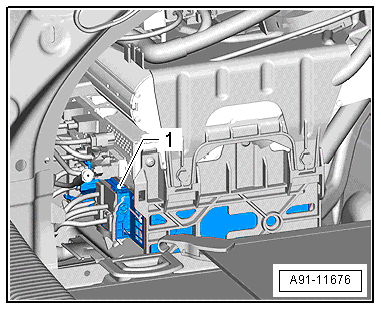
The Radio -R--1- is located behind the left luggage compartment trim panel in the lower rack.
 Note
Note
If replacing the control module, select the "Replace Control Module" function on the Vehicle Diagnostic Tester.
Removing
- Turn off the ignition and all electrical consumers and remove the ignition key.
- Open the left storage compartment in the luggage compartment.
The Radio -R- is located inside the rack under the sound amplifiers. It is necessary to remove the rack in order to remove the Radio -R-.
It is necessary to remove the bracket with the sound amplifiers first in order to be able to remove the rack.
- Unlock and disconnect the connectors from the control modules.
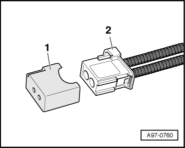
- Insert the Fiber-Optic Repair Set - Connector Protective Caps -VAS6223/9--1- onto the MOST Bus connector -2-.
- Remove the bracket with the sound amplifiers.
- BOSE. Refer to → Chapter "Digital Sound System Control Module -J525-, Removing and Installing, BOSE, MMI, through MY 2014".
- Bang & Olufsen. Refer to → Chapter "Digital Sound System Control Module -J525-, Removing and Installing, Bang & Olufsen, through MY 2014".
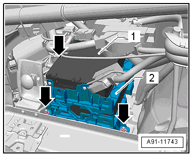
- Remove the nuts -arrows- from the rack.
- Release and disconnect the connectors from the Radio -R--1-.
- Insert the Fiber-Optic Repair Set - Connector Protective Caps -VAS6223/9--1- onto the MOST Bus connector -2-.
The wiring harness is fastened to the bottom of the rack and to the floor panel.
- Lift the rack from the storage compartment far enough until the Radio -R- can be removed from the rack.
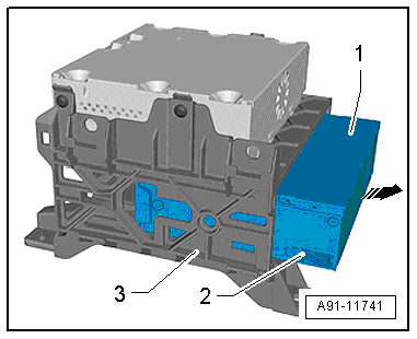
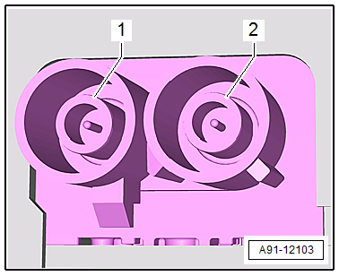
- Press the catches -2- on the right and left side of the Radio -R--1- and remove the Radio -R--1- from the rack -3-.
Installing
- Install in reverse order of removal.
Radio -R-, Removing and Installing, MMI, I8H, from MY 2015
The Radio -R- is integrated in the Information Electronics Control Module 1 -J794-. Refer to → Chapter "Information Electronics Control Module 1 -J794-, Removing and Installing".
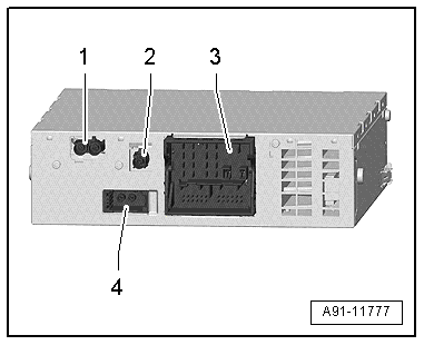
Radio Connector Assignments
Connector Assignment, RMC and 8DN
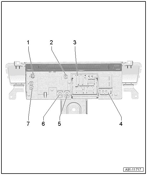
1 - Not Assigned
2 - Not Assigned
3 - Connection Block with Four Multi-Pin Connectors
4 - MOST Bus
5 - Not Assigned
6 - 4-Pin Connector -T4df- to the Front Information Display Control Head -J685-
7 - AM/FM/FM2 Antenna Connection
Note
Unlisted connector terminals are not assigned.
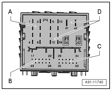
3 - Connection block with four multi-pin connectors
A - 8-Pin Connector -T8e-
1 - Right rear speaker (+)
2 - Right front speaker (+)
3 - Left front speaker (+)
4 - Left rear speaker (+)
5 - Right rear speaker (-)
6 - Right front speaker (-)
7 - Left front speaker (-)
8 - Left rear speaker (-)
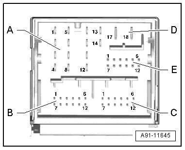
B - 12-Pin Connector -T12c-
1 - Data from Multimedia System Control Head -E380-
2 - Res BT Multimedia System Control Head -E380-
7 - Data to the Multimedia System Control Head -E380-
8 - Wake UP Multimedia System Control Head -E380-
9 - Res HU to the Multimedia System Control Head -E380-
C - 12-Pin Connector -T12-
Not assigned
D - 8-Pin Connector -T8f-
9 - Subwoofer -R211-
10 - Center Speaker -R208-
13 - Subwoofer -R211-
14 - Center Speaker -R208-
17 - Terminal 31
18 - Terminal 30
E - 12-Pin Connector -T12d-
7 - Ring-break Diagnostic Cable
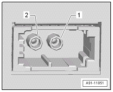
4 - MOST Bus
1 - Output
2 - Input
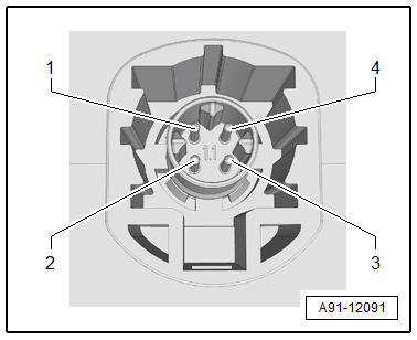
6 - 4-Pin Connector -T4df-
All pins are connected to the Front Information Display Control Head -J685-.
1 - LVDS (-)
2 - LIN
3 - LVDS (+)
4 - Ground
7 - AM/FM1/FM2 antenna connection
1 - Chamber 2, AM/FM1 from Antenna Amplifier 2 -R111-, Radio Antenna 2 -R93-
2 - Chamber 1, FM2 from Antenna Amplifier -R24-, Antenna -R11-
Connector Assignment, RMC plus and 8DP
1 - DAB Connection from Antenna Amplifier 3 -R112-, Digital Radio Antenna -R183-, ER1/ER2 and QV3
- SAT connection from Roof Antenna -R216-, Satellite Antenna -R170-, ER3 and QV8
2 - Not Assigned
3 - Connection Block with Four Multi-Pin Connectors
4 - MOST Bus
5 - 4-Pin Connector -T4z- to the External Audio Source Connection -R199-
6 - 4-Pin Connector -T4df- to the Front Information Display Control Head -J685-
7 - AM/FM/FM2 Antenna Connection
Note
Unlisted connector terminals are not assigned.
3 - Connection block with four multi-pin connectors
A - 8-Pin Connector -T8e-
1 - Right rear speaker (+)
2 - Right front speaker (+)
3 - Left front speaker (+)
4 - Left rear speaker (+)
5 - Right rear speaker (-)
6 - Right front speaker (-)
7 - Left front speaker (-)
8 - Left rear speaker (-)
B - 12-Pin Connector -T12c-
1 - Data from Multimedia System Control Head -E380-
2 - Res BT Multimedia System Control Head -E380-
3 - Not Assigned
4 - Microphone input (+) from Microphone Unit in Front Roof Module -R164-, Left Front Microphone -R140-
5 - Not Assigned
6 - Not Assigned
7 - Data to the Multimedia System Control Head -E380-
8 - Wake UP Multimedia System Control Head -E380-
9 - Res HU to the Multimedia System Control Head -E380-
10 - Not Assigned
11 - Not Assigned
12 - Microphone input (-) for the Microphone Unit in Front Roof Module -R164-, Left Front Microphone -R140-
C - 12-Pin Connector -T12e-
All pins are connected to the External Audio Source Connection -R199-.
1 - LF-In ground
2 - Right LF-In
3 - USB, +5 V
4 - USB, ground
5 - iPod, ACC Power
6 - Detect
7 - Left LF-In
8 - LF-In ground shielding
9 - CVBS cable (+)
10 - CVBS cable (-)
11 - iPod data
12 - iPod data
D - 8-Pin Connector -T8f-
9 - Subwoofer -R211-
10 - Center Speaker -R208-
13 - Subwoofer -R211-
14 - Center Speaker -R208-
17 - Terminal 31
18 - Terminal 30
E - 12-Pin Connector -T12d-
7 - Ring-break Diagnostic Cable
4 - MOST Bus
1 - Output
2 - Input
5 - 4-Pin Connector -T4z-
All pins are connected to the External Audio Source Connection -R199-.
1 - D (+)
2 - iPod recognized
3 - D (-)
4 - Ground
6 - 4-Pin Connector -T4df-
All pins are connected to the Front Information Display Control Head -J685-.
1 - LVDS (-)
2 - LIN
3 - LVDS (+)
4 - Ground
7 - antenna connection. AM/FM1/FM2
1 - Chamber 2, AM/FM1 from Antenna Amplifier 2 -R111-, Radio Antenna 2 -R93-
2 - Chamber 1, FM2 from Antenna Amplifier -R24-, Antenna -R11-
Connector Assignment, MMI, 8YQ
Radio -R-
Only ER1/ER2 and QV3
1 - AM/FM1/FM2 antenna connection
2 - DAB connection from Antenna Amplifier 3 -R112-, Digital Radio Antenna -R183-
3 - Connection block with four multi-pin connectors
4 - MOST Bus
Only ER3 and QV8
1 - AM/FM1/FM2 antenna connection
2 - SAT connection from Roof Antenna -R216-, Satellite Antenna -R170-
3 - Connection block with four multi-pin connectors
4 - MOST Bus
Note
Unlisted connector terminals are not assigned.
1 - AM/FM1/FM2 antenna connection
1 - Chamber 2, AM/FM1 from Antenna Amplifier 2 -R111-, Radio Antenna 2 -R93-
2 - Chamber 1, FM2 from Antenna Amplifier -R24-, Antenna -R11-
3 - Connection block with four multi-pin connectors
A - 8-Pin Connector -T8r-
1 - Right rear speaker (+)
2 - Right front speaker (+)
3 - Left front speaker (+)
4 - Left rear speaker (+)
5 - Right rear speaker (-)
6 - Right front speaker (-)
7 - Left front speaker (-)
8 - Left rear speaker (-)
B - 12-Pin Connector -T12-
17 - Left LF-In
18 - LF-In ground
19 - LF-In diag
21 - LF diag
22 - LF (-)
23 - Right LF-In
24 - LF-In ground shielding
27 - LF ground shielding
28 - LF (+)
C - 12-Pin Connector -T12-
Only for the Chinese version
All pins are connected to the Multimedia Control Head 2 -E499- (rear center armrest).
29 - Headphones output 1 Diag
31 - Headphones output 1/2 Diag
34 - Headphones output 2 Diag
35 - Headphones output 1 left
36 - Headphones output 1 ground
37 - Headphones output 1 right
38 - Headphones output 2 left
39 - Headphones output 2 ground
40 - Headphones output 2 right
D - 10-Pin Connector -T10i-
9 - Subwoofer -R211-
10 - Center Speaker -R208-
11 - Ring-break Diagnostic Cable
13 - Subwoofer -R211-
14 - Center Speaker -R208-
41 - Terminal 31
42 - Terminal 30
4 - MOST Bus
1 - Output
2 - Input
Connector Assignment, MMI, I8H
The Radio -R- is integrated in the Information Electronics Control Module 1 -J794-. Refer to → Wiring diagrams, Troubleshooting & Component locations.
