Audi A6 Typ 4G: Subframe, Removing and Installing
Subframe, Removing and Installing, FWD Vehicles
Special tools and workshop equipment required
- Torque Wrench 1331 5-50Nm -VAG1331-
- Torque Wrench 1332 40-200Nm -VAG1332-
- Engine and Gearbox Jack -VAS6931-
- Tensioning Strap -T10038-
- Two wood blocks
Removing
- Must be removed when assembling the brake system later. Note the following: Drive back the brake pistons. Refer to → Break System; Rep. Gr.46.
- Remove the rear wheels. Refer to → Chapter "Wheels and Tires".
- Remove the rear section from the exhaust system. Refer to → Rep. Gr.26; Exhaust Pipes/Mufflers; Overview - Muffler.
Vehicles with Steel Suspension
- Remove the coil springs. Refer to → Chapter "Spring, Removing and Installing, Coil Spring".
Vehicles with Air Suspension
- Remove air springs. Refer to → Chapter "Spring, Removing and Installing, Air Spring".
Continuation for All Vehicles
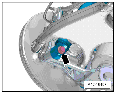
- Remove the bolt -arrow-, the washer between the wheel bearing housing and the shock absorber and then remove the left and right shock absorbers from the wheel bearing housing.
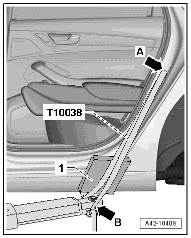
- Secure the vehicle to the hoist lifting arms -arrow B- with the Tensioning Strap -T10038- over the striker pin -arrow A-.
- Place a piece of foam rubber -1- between the sill panel and the Tensioning Strap -T10038- and then tension the Tensioning Strap -T10038-.
 Note
Note
Be careful not to scratch the sill panel.
 Caution
The vehicle could fall off the hoist if it is not secured.
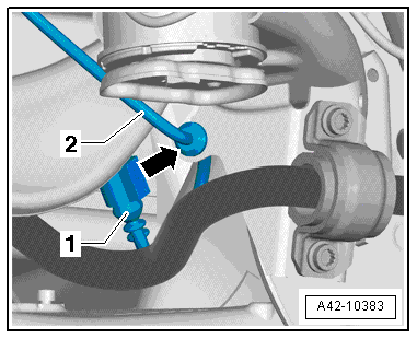
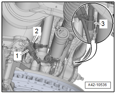
- Disconnect the connector -2- from the Left Rear ABS Wheel Speed Sensor -G46- and the Right Rear ABS Wheel Speed Sensor -G44-.
- Remove the left and right bolts -1- and the bracket with the wires from the wheel bearing housing.
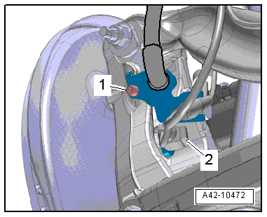
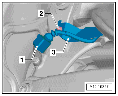
- Disconnect the connector -1- from the Left Rear Level Control System Sensor -G76- and from the Right Rear Level Control System Sensor -G77- (if equipped).
- Free up the wiring harness -2--arrow-
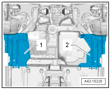
- Remove the underbody covers -1 and 2-. Refer to → Body Exterior; Rep. Gr.66; Underbody Trim Panel; Underbody Panels, Removing and Installing.
- If equipped remove the center cover -2-. Refer to → Body Exterior; Rep. Gr.66; Underbody Trim Panel; Underbody Panels, Removing and Installing.
- Remove the diagonal braces, if equipped. Refer to → Chapter "Diagonal Braces, Removing and Installing".
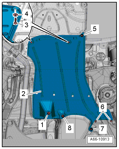
- Remove the stone chip protection -1 and 2-, if equipped.
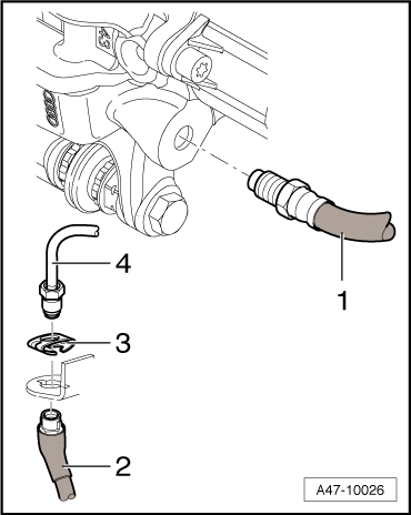
- Disconnect the right and left brake line -4- on the brake hose -2-. Refer to → Brake System; Rep. Gr.46.
Note
Ignore Item -1-.
- Secure the subframe. Refer to → Chapter "Subframe, Securing, FWD".
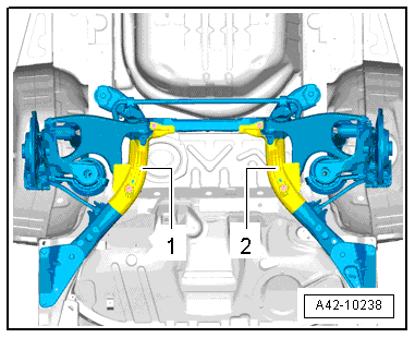
- Remove the left and right bolts -arrow-.
- Carefully lower subframe with components. Pay attention to any wires that may be hanging down.
Installing
Install in reverse order of removal. Note the following:
Note
- Bonded rubber bushings have a limited range of motion. Only tighten suspension bolts when vehicle is in curb weight or control position.
- For lifting the wheel bearing into curb weight position, vehicles with steel suspension. Refer to → Chapter "Wheel Bearing in Curb Weight, Lifting Vehicles with Coil Spring".
- For vehicles with air spring suspension, lift wheel suspension in control position. Refer to → Chapter "Wheel Bearing in Control Position, Lifting Vehicles with Air Suspension".
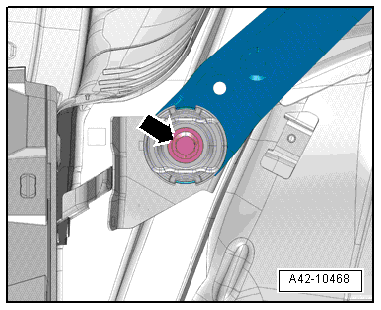
- Tighten the left and right bolts -arrow-.
Note
Only install the coil springs or air springs when the subframe bolts have been tightened to the specification.
- Remove the Subframe Locating Pins -T40242-. Refer to → Chapter "Subframe, Securing, Vehicles with AWD".
- Install the coil springs (refer to → Chapter "Spring, Removing and Installing, Coil Spring") or air springs (refer to → Chapter "Spring, Removing and Installing, Air Spring").
- Remove the right and left brake hose. Refer to → Brake System; Rep. Gr.46.
- Install the shock absorber. Refer to → Chapter "Shock Absorber, Removing and Installing".
- Install the underbody covers. Refer to → Body Exterior; Rep. Gr.66; Underbody Trim Panel; Overview - Underbody Panels.
- If equipped install the center cover -2-. Refer to → Body Exterior; Rep. Gr.66; Underbody Trim Panel; Overview - Underbody Panels.
- Install the diagonal braces (if equipped). Refer to → Chapter "Diagonal Braces, Removing and Installing".
- Install the rear section from the exhaust system. Refer to → Rep. Gr.26; Exhaust Pipes/Mufflers; Overview - Muffler.
- Bleed the brake system. Refer to → Brake System; Rep. Gr.47.
- Install rear wheels. Refer to → Chapter "Wheels and Tires".
- To determine if an axle alignment is required, see Table. Refer to → Chapter "Evaluating Need for Axle Alignment".
- If the subframe was removed and installed again, then the control position must be programmed again on vehicles with air suspension. Start the program on the Vehicle Diagnostic Tester in Guided Functions.
- It is necessary to reprogram the control position on vehicles with air suspension if the vehicle level sensor or the linkage on the vehicle level sensor was loosened during installation. Start the program on the Vehicle Diagnostic Tester in Guided Functions.
- If the control position was reprogrammed on vehicles with lane assist, the Camera Control Module -J852- must be calibrated again. Refer to → Chapter "Driver Assistance Systems Front Camera, Calibrating".
Subframe, Removing and Installing, AWD Vehicles
Special tools and workshop equipment required
- Torque Wrench 1331 5-50Nm -VAG1331-
- Torque Wrench 1332 40-200Nm -VAG1332-
- Engine and Gearbox Jack -VAS6931-
- Tensioning Strap -T10038-
Removing
Note
- For later assembly work where the drive axle to wheel hub threaded connection must be loosened, note that it must not be done while the vehicle is resting on its wheels. Loosen the connection between the drive axle and wheel hub. Refer to → Chapter "Drive Axle Threaded Connection, Loosening and Tightening".
- Must be removed when assembling the brake system later. Note the following: Drive back the brake pistons. Refer to → Break System; Rep. Gr.46.
- Remove the rear wheels. Refer to → Chapter "Wheels and Tires".
- Remove the rear section from the exhaust system. Refer to → Rep. Gr.26; Exhaust Pipes/Mufflers; Overview - Muffler.
- Remove the drive axle from the rear final drive and tie it up. Refer to → Rear Final Drive 0BC, 0BD, 0BE, 0BF; Rep. Gr.39.
Vehicles with Steel Suspension
- Remove the coil springs. Refer to → Chapter "Spring, Removing and Installing, Coil Spring".
Vehicles with Air Suspension
- Remove air springs. Refer to → Chapter "Spring, Removing and Installing, Air Spring".
Continuation for All Vehicles
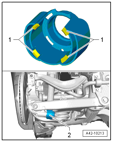
- Release the retaining tabs -1- and remove the stone deflector -2-.
- Remove the bolt -arrow-, the washer between the wheel bearing housing and the shock absorber and then remove the left and right shock absorbers from the wheel bearing housing.
- Secure the vehicle to the hoist lifting arms -arrow B- with the Tensioning Strap -T10038- over the striker pin -arrow A-.
- Place a piece of foam rubber -1- between the sill panel and the Tensioning Strap -T10038- and then tension the Tensioning Strap -T10038-.
Note
Be careful not to scratch the sill panel.
Caution
The vehicle could fall off the hoist if it is not secured.
- If equipped remove the center cover -2-. Refer to → Body Exterior; Rep. Gr.66; Underbody Trim Panel; Underbody Panels, Removing and Installing.
- If the vehicles as a sport differential, remove the bolts -arrows- and remove the bracket -1- from the rear final drive.
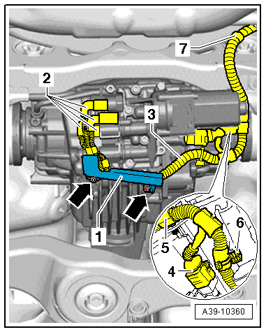
Note
Mark for connecting the connectors -2- to the oil pressure sensor, the oil temperature sensor and the clutch valves later.
- Disconnect the connectors -2- from the oil pressure and temperature sensors and the clutch valves.
- Disconnect the connector -4- from the All Wheel Drive Pump -V415-.
- Unclip the wiring harness -3- from the final drive and the subframe -5 through 7- and tie it up.
- Disconnect the connector -1- from the Left Rear ABS Wheel Speed Sensor -G46- and the Right Rear ABS Wheel Speed Sensor -G44-.
- Free up the wires.
- Remove the left and right bolts -2- and free up the bracket -3- from the subframe.
- Disconnect the left and right connectors:
1 - For the rear brake pad wear sensor
2 - For the parking brake motor
3 - For the Dynamic Ride Control (DRC) system on Audi RS6
- Free up the wires.
- Disconnect the connector -1- from the Left Rear Level Control System Sensor -G76- and from the Right Rear Level Control System Sensor -G77-.
- Free up the wiring harness -2--arrow-
- Remove the underbody covers -1 and 2-. Refer to → Body Exterior; Rep. Gr.66; Underbody Trim Panel; Underbody Panels, Removing and Installing.
- Remove the diagonal braces, if equipped. Refer to → Chapter "Diagonal Braces, Removing and Installing".
- Remove the stone chip protection -1, 2 and 3-, if equipped.
- Disconnect the right and left brake line -4- on the brake hose -2-. Refer to → Brake System; Rep. Gr.46.
Note
Ignore Item -1-.
- Secure the subframe. Refer to → Chapter "Subframe, Securing, Vehicles with AWD".
- Remove the left and right bolts -arrow-.
- Carefully lower subframe with components. Pay attention to any wires that may be hanging down.
Installing
Install in reverse order of removal. Note the following:
Note
- Bonded rubber bushings have a limited range of motion. Only tighten suspension bolts when vehicle is in curb weight or control position.
- For lifting the wheel bearing into curb weight position, vehicles with steel suspension. Refer to → Chapter "Wheel Bearing in Curb Weight, Lifting Vehicles with Coil Spring".
- For vehicles with air spring suspension, lift wheel suspension in control position. Refer to → Chapter "Wheel Bearing in Control Position, Lifting Vehicles with Air Suspension".
- Tighten the left and right bolts -arrow-.
Note
Only install the coil springs or air springs when the subframe bolts have been tightened to the specification.
- Remove the Subframe Locating Pins -T40242-. Refer to → Chapter "Subframe, Securing, Vehicles with AWD".
- Install the coil springs (refer to → Chapter "Spring, Removing and Installing, Coil Spring") or air springs (refer to → Chapter "Spring, Removing and Installing, Air Spring").
- Remove the right and left brake hose. Refer to → Brake System; Rep. Gr.46.
- Install shock absorber. Refer to → Chapter "Shock Absorber, Removing and Installing".
- Attach the drive axle to the rear final drive. Refer to → Rear Final Drive 0BC, 0BD, 0BE, 0BF; Rep. Gr.39.
- Install the underbody covers. Refer to → Body Exterior; Rep. Gr.66; Underbody Trim Panel; Overview - Underbody Panels.
- If equipped install the center cover -2-. Refer to → Body Exterior; Rep. Gr.66; Underbody Trim Panel; Overview - Underbody Panels.
- Install the diagonal braces (if equipped). Refer to → Chapter "Diagonal Braces, Removing and Installing".
- Install the rear section from the exhaust system. Refer to → Rep. Gr.26; Exhaust Pipes/Mufflers; Overview - Muffler.
- Bleed the brake system. Refer to → Brake System; Rep. Gr.47.
- Install rear wheels. Refer to → Chapter "Wheels and Tires".
- Perform a road test. An axle alignment may be necessary. Refer to → Chapter "Subframe, Securing, FWD".
- If the subframe was removed and installed again, then the control position must be programmed again on vehicles with air suspension. Start the program on the Vehicle Diagnostic Tester in Guided Functions.
- It is necessary to reprogram the control position on vehicles with air suspension if the vehicle level sensor or the linkage on the vehicle level sensor was loosened during installation. Start the program on the Vehicle Diagnostic Tester in Guided Functions.
- If the control position was reprogrammed on vehicles with lane assist, the Camera Control Module -J852- must be calibrated again. Refer to → Chapter "Driver Assistance Systems Front Camera, Calibrating".
Diagonal Braces, Removing and Installing
Removing
- Remove the underbody covers -1 and 2-. Refer to → Body Exterior; Rep. Gr.66; Underbody Trim Panel; Underbody Panels, Removing and Installing.
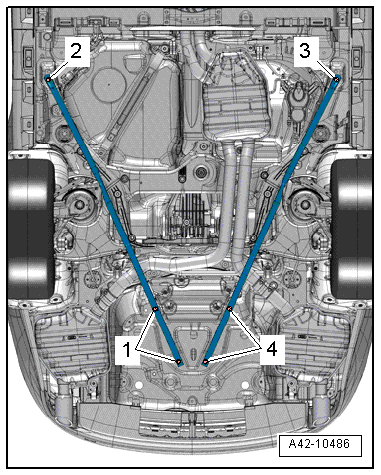
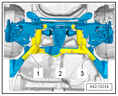
- Remove the bolts -1 through 4- and the diagonal brace.
Installing
Install in reverse order of removal.