Audi A6 Typ 4G: Refrigerant Circuit Components
 Caution
Non-approved tools or materials such as leak sealing additives can cause damage or malfunctions in the system.
Only use tools and materials approved by the manufacturer.
The warranty is voided if non-approved tools or materials are used.
- Any refrigerant circuit components submitted for quality observation must be sealed (use the caps that come with the replacement part).
- Replace damaged or leaking components of the refrigerant circuit. Refer to → Chapter "Refrigerant Circuit Components, Replacing".
 Note
Note
To date, the following replacement parts (A/C compressor, reservoir, evaporator and condenser) are filled with nitrogen gas. This charge is being gradually discontinued. Little or no pressure equalization is therefore noticeable on unscrewing sealing plugs from replacement parts.
Refrigerant Circuit Components Allocation, High and Low Pressure Sides
General Information
High pressure side are the condenser, receiver/dryer and restrictor or expansion valve to separate the high and low pressure liquid ends.
High pressure results from the restrictor or expansion valve forming a constriction and causing the refrigerant to accumulate, thus leading to an increase in pressure and temperature.
Excess pressure occurs if too much refrigerant or refrigerant oil is used, the condenser is contaminated, the radiator fan is malfunctioning, the system is blocked or there is moisture in the refrigerant circuit (icing-up of restrictor or expansion valve).
Low pressure side are the evaporator, reservoir, evaporator temperature sensor and A/C compressor to separate high and low pressure gas ends.
A drop in system pressure can be caused by loss of refrigerant, the restrictor or expansion valve (no constriction), a malfunctioning A/C compressor or an iced-up evaporator.
Mechanically Driven A/C Compressor
The A/C compressor is driven by a ribbed belt or a input shaft, which is driven by the vehicle engine.
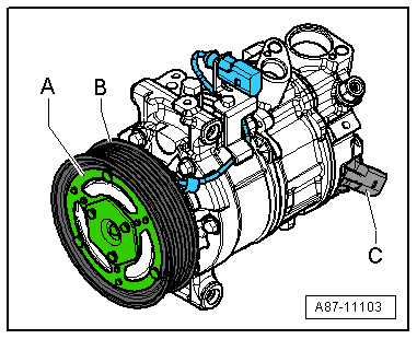
A/C Compressor with A/C Clutch
- An electromagnetic clutch -A- attached to A/C compressor provides the power link between the ribbed belt pulley -B- and A/C compressor crankshaft with A/C system switched on.
- An overload safeguard attached to the clutch plate or in the A/C compressor solenoid coil is tripped if the compressor does not move freely, thus protecting the belt drive against overload.
A/C Compressor without A/C Clutch
- An overload safeguard attached to the pulley of the compressor -B- is tripped if the compressor does not move freely, thus protecting the belt drive against overload.
All A/C Clutch
The A/C compressor extracts the refrigerant gas from the evaporator, compresses it and relays it to the condenser.
Note
- The A/C compressor contains refrigerant oil, which can be mixed with refrigerant R134a under any temperature.
- The data plate lists the type of refrigerant required for the A/C compressor. A regulator valve regulates pressure within the specified range (control characteristics) on the low pressure side.
- A/C compressors with or without an A/C clutch are currently controlled externally by a regulator valve -C-.
- On A/C compressors without an A/C clutch, the engine is only to be started following complete assembly of the refrigerant circuit.
- So that the A/C compressor does not get damaged when the refrigerant circuit is empty, the A/C clutch is turned off and the A/C Compressor Regulator Valve -N280- is no longer activated (A/C compressor runs at idle with engine).
- If the refrigerant circuit is empty, a A/C compressor without A/C Clutch -N25- with (A/C Compressor Regulator Valve -N280-) is switched to internal lubrication by way of a valve.
- Depending on the A/C compressor version, there may be a valve installed on the high pressure side of the A/C compressor, which prevents the liquid refrigerant from flowing back into the compressor once the A/C is turned off. If an A/C compressor with this valve is installed in a vehicle with a refrigerant circuit having an expansion valve, then it may take some time until the pressure in the high pressure side decreases (the expansion is cold and the pressure in the low pressure side quickly increases after it is turned off, the expansion valve closes and the refrigerant flows slowly into the low pressure side). If the A/C compressor is switched on, the pressure on the low pressure side goes down, the expansion valve open and the refrigerant can flow of the low pressure side.
- The electromagnetic clutch -A- is activated only when the regulator valve -C- is activated on an A/C compressor with an electromagnetic clutch -A- and with a regulator valve -C-. Refer to → Heating, Ventilation and Air Conditioning; Rep. Gr.87; System Overview - Refrigerant Circuit.
Electrically Driven A/C Compressor for Vehicles with High Voltage System
Vehicles with a High-Voltage System (Hybrid Vehicles)
Extremely Dangerous Due to High-Voltage
The high-voltage system is under high-voltage. Death or serious bodily injury by electric shock.
- Individuals with electronic/medical life- and health sustaining machines in or on their person cannot perform any work on high-voltage systems. Life- and health sustaining machines are for example pain killer pumps, implanted defibrillators, pacemakers, insulin pumps, and hearing aids.
- Have the high-voltage system de-energized by a qualified person.
There is a Risk Of Injury from the Engine Starting Unexpectedly
On electric - hybrid vehicles an active ready mode is difficult to identify. Parts of the body can be clamped or pulled.
- Turn off the ignition.
- Place the ignition key outside of the vehicle interior.
Risk of Damaging the High-Voltage Cables
Misuse can damage the insulation of high-voltage cables or high-voltage connectors.
- Never support objects on the high-voltage cables and the high-voltage connectors.
- Never support tools on the high-voltage cables and the high-voltage connectors.
- Never sharply bend or kink the high-voltage cables.
- When connecting pay attention to the coding of the high-voltage connectors.
- For all procedures on vehicles with high-voltage system pay attention to the additional warning message for these vehicles. Refer to → Chapter "Warnings when Working on Vehicles with High Voltage System".
- If procedures are necessary near components of the high-voltage system "perform a visual inspection of the damage of the high-voltage components and lines". Refer to → Chapter "Performing a Visual Inspection of Damage to High Voltage Components and Cables".
- If work on the components of the high-voltage system is necessity, de-energize the high-voltage system. Refer to → Rep. Gr.93; High-Voltage System, De-Energizing or → Electrical Equipment; Rep. Gr.93; High-Voltage System, De-Energizing.
- Charge the vehicle battery, for example, using the Battery Charger -VAS5904- in the battery support mode to minimize the number of automatic starts during the test- and measuring procedures while the ready mode is active. Refer to → Electrical Equipment General Information; Rep. Gr.27; Battery, Charging and → High Voltage Vehicle General Information; Rep. Gr.93; High-Voltage System General Warnings.
- For testing and measurement procedures that require the ready mode to be active or the ignition to be switched on, the selector lever must be in the "P" position and the parking brake must be activated. The required tools must be placed so that they do not come into contact with any rotating components in the engine and they must also not go into the vicinity of the rotating components when the engine is running.
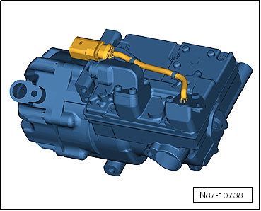
Electrically-Driven A/C Compressor
 WARNING
Risk of short circuit
The A/C compressor works with up to 288 volts at 800 to 8,600 RPM.
Do not touch the A/C compressor when the ignition is turned on or when the drive machines are activated because of the short circuit risk.
- The A/C compressor extracts the refrigerant gas from the evaporator, compresses it and relays it to the condenser.
- The electric motor for the A/C compressor is powered with voltage from the Electric Drive Power and Control Electronics -JX1-.
- The A/C Compressor Control Module -J842- integrated in the A/C compressor controls the rotation and thereby the output for the A/C compressor (Electrical A/C Compressor -V470-) corresponding with the Data bus receiving requirements. Use the Vehicle Diagnostic Tester in the "Guided Fault Finding" Function for the A/C System and the Battery Regulation.
- There is no A/C Compressor Regulator Valve -N280- installed in the electrically-driven A/C compressor.
- Check the attachment points on the A/C compressor and the bracket prior to installation. The contact surfaces must be clean and free of rust and grease. Otherwise, repair the contact surfaces with the Contact Surface Cleaning Set -VAS6410-. Refer to → Electrical Equipment General Information; Rep. Gr.97; Wire and Connector Repair.
Note
- Check the amount of refrigerant oil in the new A/C compressor if the A/C Compressor Control Module -J842- is faulty. Do not flush the refrigerant circuit with R134a.
- The A/C Compressor Control Module -J842- and the Electrical A/C Compressor -V470- are one component and are currently not able to be separated.
- There is no A/C Compressor Regulator Valve -N280- installed in the electrically driven A/C compressor. The A/C compressor output is regulated externally by the A/C compressor speed. Refer to → Wiring diagrams, Troubleshooting & Component locations and use the Vehicle Diagnostic Tester in the "Guided Fault Finding" Function for the A/C System and the Battery Regulation.
- The electrically-driven A/C compressor functions according to the principle of a spiral charger (similar to a G-charger).
- The A/C compressor contains refrigerant oil, which can be mixed with refrigerant R134a under any temperature.
- The data plate lists the type of refrigerant required for the A/C compressor.
- The installed electronics are controlled by the speed of the A/C compressor power output (and the pressure on the low pressure side) within the specified range (control characteristic).
- The engine should only be started if the refrigerant circuit is completely assembled.
- The A/C compressor is equipped with a protected oil supply, this prevents A/C compressor damage in the event that the system is empty. This means that approximately 40 to 50 cm3 of refrigerant oil remains in the A/C compressor.
- The electrically-driven A/C compressor has a relief valve like the mechanically-driven A/C compressor.
- Hybrid drive on vehicles with battery cooling is only possible with a fully charged A/C system in which there are no stored errors. Use the Vehicle Diagnostic Tester in the "Guided Fault Finding" Function for the A/C System and the Battery Regulation.
- After the installation of the electrically-driven A/C compressor and the subsequent filling of the refrigerant circuit, start the A/C compressor for the first time using the "compressor intake" function for the basic setting. The A/C compressor may otherwise become damaged if before installation, refrigerant oil was improperly stored in the A/C compressor compression chamber. Use the Vehicle Diagnostic Tester in the "Guided Fault Finding" Function for the A/C System and the Battery Regulation.
- Only activate the electrically-driven A/C compressor when the refrigerant circuit is filled. The A/C compressor may become damaged if the A/C compressor is run when the refrigerant circuit is empty. Use the Vehicle Diagnostic Tester in the "Guided Fault Finding" Function for the A/C System and the Battery Regulation.
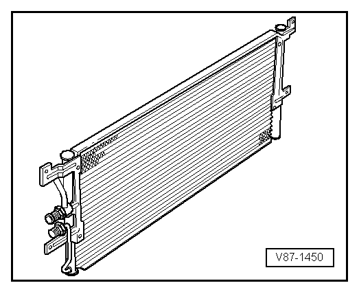
Condenser
The condenser conducts heat from compressed refrigerant gas to the ambient air.
This condenses the refrigerant gas to fluid.
Note
- Depending on the version of the refrigerant circuit, the receiver/dryer is installed (integrated) either on the condenser or inside the condenser. Refer to → Heating, Ventilation and Air Conditioning; Rep. Gr.87; System Overview - Refrigerant Circuit (vehicle-specific repair manual) and the Parts Catalog.
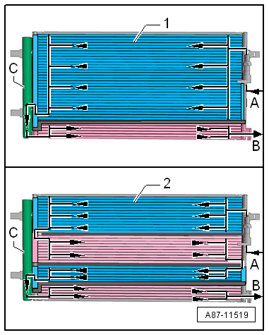
- The condenser is available in different versions and can be differentiated only by the part number on the outside. For version -1-, the condenser is divided into two areas "2 way condenser". For version -2-, the condenser is divided into four areas "4 way condenser".
- This illustration shows a condenser with the receiver/dryer -C- installed.
- The gaseous refrigerant enters at the connection -A- into the condenser. The refrigerant is then cooled inside the condenser and becomes fluid.
- The liquid refrigerant collects in the receiver/dryer -C- (with dryer) and flows through the lower cooling area towards the connection -B-.
- Depending on the design of the condenser (interior volumes, delivery flow, etc.), the amount of the refrigerant that is needed to fill the refrigerant circuit may vary. Therefore always be sure of the correct version and allocation for the condenser. Refer to → Chapter "Refrigerant R134a Capacities" and the Parts Catalog.
Evaporator
The evaporator is available in different versions. Depending on the version and the function, the necessary heat energy of the air flow (for example, an evaporator in the A/C unit or in the battery cooling module) or flowing coolant (for example near the high voltage battery heat exchanger) is extracted for refrigerant evaporation. Refer to → Heating, Ventilation and Air Conditioning; Rep. Gr.87; System Overview - Refrigerant Circuit (vehicle-specific repair manual).
Note
Two versions of evaporator are described.
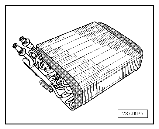
Evaporator in A/C Unit (or in Battery Cooling Module)
The fluid refrigerant evaporates in the evaporator pipe coils. The heat required for this is extracted from the air flowing on the evaporator ribbing. The air cools off. Refrigerant evaporates and is extracted with the absorbed heat by the A/C compressor.
A defined amount of refrigerant is supplied to the evaporator by a restrictor or expansion valve. In systems with expansion valve, the throughput is regulated so that only gaseous refrigerant escapes the evaporator outlet.
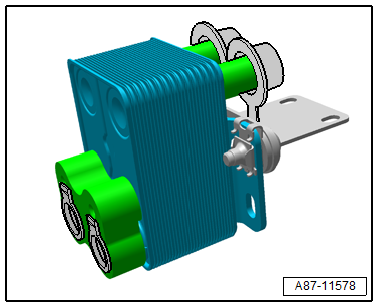
Evaporator/High Voltage Battery Heat Exchanger (Chiller)
The liquid refrigerant evaporates in evaporator (heat exchanger). The heat required for this is extracted from the flowing refrigerant. The coolant cools, the refrigerant evaporates and is extracted with the absorbed heat by the A/C compressor.
A defined amount of refrigerant is supplied to the evaporator by a restrictor (or expansion valve) and a shut off valve. The throughput of the refrigerant (for example the coolant) is regulated so that only gaseous refrigerant escapes the evaporator outlet. Refer to → Heating, Ventilation and Air Conditioning; Rep. Gr.87; System Overview - Refrigerant Circuit (vehicle-specific repair manual).
Heat Pump Operation Heater Core
The gaseous or vaporous refrigerant that is compressed by the A/C compressor is liquefied in the A/C compressor -A- and at the same time released heat is transferred to the coolant flowing by. Refer to → Heating, Ventilation and Air Conditioning; Rep. Gr.87; Refrigerant Circuit; System Overview - Refrigerant Circuit.
Fluid Collector
In some operating conditions (for example heat pump operation) the receiver/dryer (for example on the condenser) is not incorporated in the refrigerant circuit. The fluid collector -B- collects the refrigerant, and saves it if a specific quantity of refrigerant is not needed and directs it in an uninterrupted stream to the expansion valve (in front of the evaporator in the heater and A/C unit) or to the heat exchanger in the refrigerant circuit of the high-voltage system. Refer to → Heating, Ventilation and Air Conditioning; Rep. Gr.87; Refrigerant Circuit; System Overview - Refrigerant Circuit.
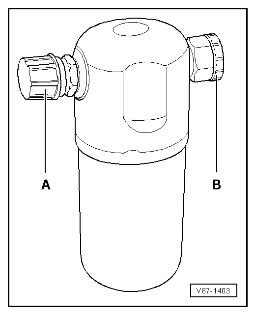
Reservoir
The reservoir collects the vaporized and gaseous mixture coming from the evaporator to ensure the compressor only receives gaseous refrigerant. Gaseous refrigerant is formed from the vapor.
The refrigerant oil flowing in the circuit is not retained in the reservoir as it has an oil drilling.
Moisture which has entered the refrigerant circuit during repairs will be collected by a filter (desiccant bag) in the reservoir.
Gaseous refrigerant is extracted with oil by the A/C compressor.
Note
- Replace the reservoir if refrigerant circuit has been open for a long time (beyond the normal repair time) and moisture has penetrated inside, or if required due to a specific complaint. Refer to → Chapter "Refrigerant Circuit Components, Replacing".
- Remove the sealing plugs -A- and -B- only immediately before installing.
- A desiccant bag in an unsealed reservoir is saturated with moisture after a short period of time and unusable.
- When installing, note arrow for direction of flow if necessary.
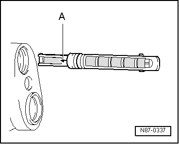
Restrictor
Restrictor in Front of the Evaporator
The restrictor creates a constriction. This restriction reduces the flow and creates high and low pressure sides in the refrigerant circuit. Before the restrictor the refrigerant which is under a higher pressure is warm. After the restrictor the refrigerant which is under a low pressure is cold. Before the restriction there is a strainer for contaminants and after the restriction there is a strainer, to atomize the refrigerant before it reaches the evaporator.
Note
- Arrow -A- on restrictor points to the evaporator.
- Replace after each opening of the circuit.
- There are different versions, therefore pay attention to the different customer service information sources. Refer to → Heating, Ventilation and Air Conditioning; Rep. Gr.87; System Overview - Refrigerant Circuit and (vehicle-specific repair manual) and to the Parts Catalog.
Restrictor in Front of the High Voltage Battery Heat Exchanger (Chiller)
The restrictor creates a constriction. This restriction reduces the flow and creates high and low pressure sides in the refrigerant circuit. Before the restrictor the refrigerant which is under a higher pressure is warm. After the restrictor the refrigerant which is under a low pressure is cold.
Note
- The illustration shows a refrigerant line -A- with a fixed installed restrictor -B- (without a strainer)
- The diameter of the illustrated variable orifice -B- is approximately 0.7 mm. Depending on the version of the refrigerant line this constriction is either installed fixed in the refrigerant line or only inserted. For the inserted version a strainer for flowing deposits may be installed, which can be blocked by the variable orifice.
- Before installing check for debris and if necessary clean or replace.
- There are different versions, therefore pay attention to the different customer service information sources. Refer to → Heating, Ventilation and Air Conditioning; Rep. Gr.87; System Overview - Refrigerant Circuit and (vehicle-specific repair manual) and to the Parts Catalog.
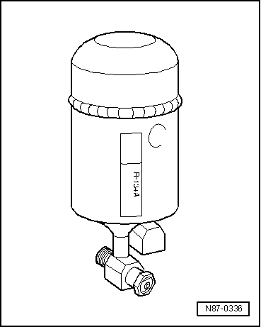
Receiver/Dryer
The receiver/dryer collects the fluid drops and then directs them in an uninterrupted stream to the expansion valve. Moisture which has entered the refrigerant circuit during repairs will be collected by the desiccant bag in the receiver/dryer.
Note
- Replace the receiver/dryer if refrigerant circuit has been open for a long time (beyond the normal repair time) and moisture has penetrated inside, or if required due to a specific complaint. Refer to → Chapter "Refrigerant Circuit Components, Replacing".
- Only remove sealing plugs shortly before installation.
- A desiccant bag in an unsealed receiver/dryer becomes saturated with moisture after a short period of time and unusable.
- When installing, note arrow for direction of flow if necessary.
- Depending on the version of the refrigerant circuit, the receiver/dryer is also installed (integrated) either on the condenser or inside the condenser. Refer to → Heating, Ventilation and Air Conditioning; Rep. Gr.87; System Overview - Refrigerant Circuit (vehicle-specific repair manual) and the Parts Catalog.
- The procedure is different for each complaint depending on the version of the receiver/dryer and the dryer cartridge. If the receiver/dryer, for example, is attached to the condenser, then it can be replaced complete with the drying cartridge. If the receiver/dryer, for example, is inside the condenser, then the dryer cartridge, and any possible additional filters, can be replaced separately, on most versions. If the receiver/dryer is inside the condenser and there is absolutely no way to replace the reservoir or the dry cartridge individually, then the entire condenser must be replaced. Refer to →Heating, Ventilation and Air Conditioning; Rep. Gr.87 and →Heating, Ventilation and Air Conditioning; Rep. Gr.87 (vehicle-specific repair manual) and Parts Catalog.
- Depending on the construction of the refrigerant circuit, the receiver can also be secured onto the condenser. Refer to → Heating, Ventilation and Air Conditioning; Rep. Gr.87; System Overview - Refrigerant Circuit (vehicle-specific repair manual) and the Parts Catalog.
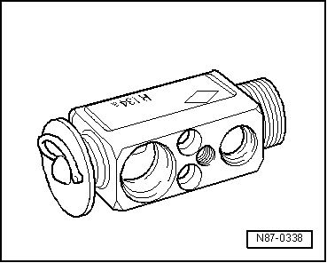
Expansion Valve
The expansion valve atomizes the streaming refrigerant and controls the flow quantity so that the vapor is gaseous only at the evaporator outlet, depending on the heat transmission.
Note
- Be sure to use the correct part number when replacing the expansion valve. Refer to the Parts Catalog.
- Different characteristic curves matched to the appropriate circuit. Refer to → Heating, Ventilation and Air Conditioning; Rep. Gr.87; System Overview - Refrigerant Circuit (vehicle-specific repair manual) and the Parts Catalog.
- Depending on the A/C compressor version, there may be a valve installed on the high pressure side of the A/C compressor, which prevents the liquid refrigerant from flowing back into the compressor once the A/C is turned off. If an A/C compressor with this valve is installed in a vehicle with a refrigerant circuit having an expansion valve, then it may take some time until the pressure in the high pressure side decreases (the expansion is cold and the pressure in the low pressure side quickly increases after it is turned off, the expansion valve closes and the refrigerant flows slowly into the low pressure side). If the A/C compressor is switched on, the pressure on the low pressure side goes down, the expansion valve open and the refrigerant can flow of the low pressure side.
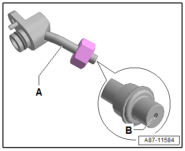
Expansion Valve with Shut-Off Valve
Note
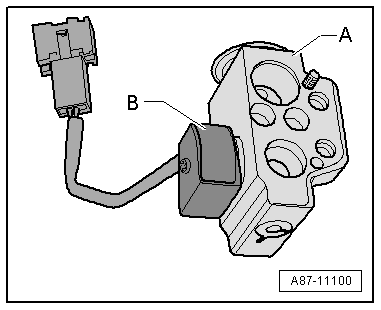
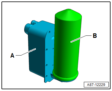
There are different versions of the shut-off valve with different functions and with different names. The following illustrated Hybrid Battery Refrigerant Shut-Off Valve 2 -N517- is for example installed on an Audi Q7 hybrid in the battery cooling module. Refer to → Heating, Ventilation and Air Conditioning; Rep. Gr.87; Refrigerant Circuit; System Overview - Refrigerant Circuit.
- The expansion valve -A- with the Hybrid Battery Refrigerant Shut-Off Valve 2 -N517--B- atomizes the streaming refrigerant and regulates the refrigerant flow rate to the evaporator in the battery cooling module for the Hybrid Battery Unit -AX1- so that the vapor becomes gaseous only at the evaporator output, depending on the heat transmission.
- If the Hybrid Battery Refrigerant Shut-Off Valve 2 -N517--B- is activated by the electronics and is open, it lets refrigerant flow through the expansion valve -A- to the evaporator in the battery cooling module.
- The expansion valve -A- with the Hybrid Battery Refrigerant Shut-Off Valve 2 -N517--B- is installed on vehicles with a battery cooling module. It is activated when the A/C system is in operation, if it is necessary to cool the Hybrid Battery Unit -AX1-.
- If the Hybrid Battery Refrigerant Shut-Off Valve 2 -N517--B- is activated by the electronics (for example, by the Battery Regulation Control Module -J840-), it is open and lets the refrigerant flow according to its control characteristic toward the evaporator in the battery cooling module.
- The Hybrid Battery Refrigerant Shut-Off Valve 2 -N517--B- attached to the expansion valve -A- is activated, for example, by the Battery Regulation Control Module -J840-. Refer to → Wiring diagrams, Troubleshooting & Component locations. Use the Vehicle Diagnostic Tester in the "Guided Fault Finding" Function for the A/C System and the Battery Regulation.
- If, for a vehicle with two evaporators (one in the A/C unit and one in the battery cooling module, for example on the Q5 Hybrid), the measured temperature on one of the evaporators corresponds to the specified value or the specified value falls short, but does not reach the required specified value on the other evaporator, the following adjustment is performed: the Battery Regulation Control Module -J840- activates the electric A/C compressor with increased speed (thereby increasing the A/C system cooling output and decreasing the pressure on the low pressure side as well as the evaporator temperature) via the Electric Drive Power and Control Electronics -JX1- and the A/C Compressor Control Module -J842-. If the specified value for the temperature falls short at one of the evaporators, the Battery Regulation Control Module -J840- activates the Hybrid Battery Refrigerant Shut-Off Valve 1 -N516- or the Hybrid Battery Refrigerant Shut-Off Valve 2 -N517-, so that the evaporator which is too cold is no longer supplied with refrigerant. Use the Vehicle Diagnostic Tester in the "Guided Fault Finding" Function for the A/C System.