Audi A6 Typ 4G: Effects Speakers, Removing and Installing
Left/Right Effects Speaker -R209-/-R210-, Removing and Installing, BOSE
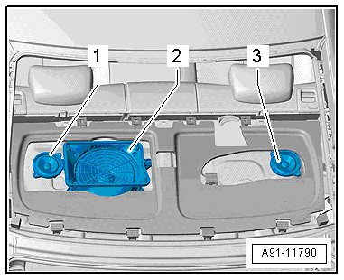
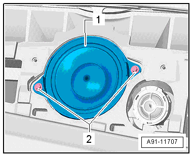
The Left Effects Speaker -R209--1-/Right Effects Speaker -R210--2- are located in the rear shelf on the left and right sides. The Effects Speakers are attached to the speaker trim.
Removing
- Turn off the ignition and all electrical consumers and remove the ignition key.
- Remove the speaker trim. Refer to → Body Interior; Rep. Gr.70; Passenger Compartment Trim; Speaker Trim, Removing and Installing.
- Release and disconnect the connector from the Left Effects Speaker -R209-.
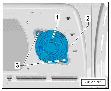
- Remove the bolts -3- from the Left Effects Speaker -R209--1-.
- Remove the Left Effects Speaker -R209--1- from the speaker trim -2-.
Installing
- Install in reverse order of removal.
Left/Right Effects Speaker -R209-/-R210-, Removing and Installing, Bang & Olufsen
The Left Effects Speaker -R209-/Right Effects Speaker -R210- are located in the rear shelf on the left and right side.
Removing
- Turn off the ignition and all electrical consumers and remove the ignition key.
- Remove the rear shelf. Refer to → Body Interior; Rep. Gr.70; Passenger Compartment Trim; Rear Shelf, Removing and Installing.
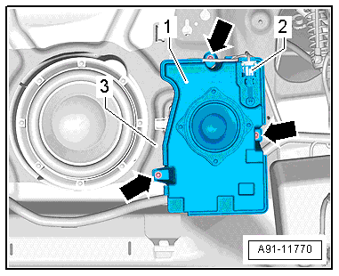
- Remove the bolts -arrows- from the Right Effects Speaker -R209--1-.
- Release and disconnect the connector -2- from the Left Effects Speaker -R209--1-.
- Remove the Left Effects Speaker -R209--1- upward from the rear shelf -3-.
Installing
- Install in reverse order of removal.
Center Speaker, Removing and Installing
Center Speaker -R208-, Removing and Installing
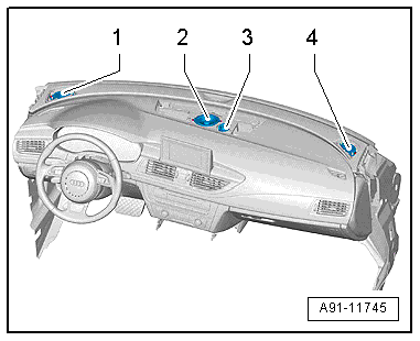
The Center Speaker -R208--2- is located in the center of the instrument panel.
Removing
- Turn off the ignition and all electrical consumers and remove the ignition key.
- Remove the center speaker trim. Refer to → Body Interior; Rep. Gr.70; Instrument Panel; Speaker Trim, Removing and Installing.
- Remove the screws -2- from the Center Speaker -R208--1-.
- Release and disconnect the connector from the Center Speaker -R208--1-.
- Remove the Center Speaker -R208--1- from the instrument panel.
Installing
- Install in reverse order of removal.
Center Speaker 2 -R219-, Removing and Installing, Bang & Olufsen
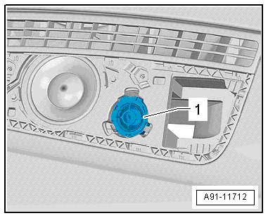
The Center Speaker 2 -R219--3- is located in the center of the front instrument panel.
Removing
- Turn off the ignition and all electrical consumers and remove the ignition key.
- Remove the center speaker trim. Refer to → Body Interior; Rep. Gr.70; Instrument Panel; Speaker Trim, Removing and Installing.
- Unclip the Center Speaker 2 -R219--1- from the instrument panel.
- Release and disconnect the connector from the Center Speaker 2 -R219--1-.
Installing
- Install in reverse order of removal.
ANC Microphones, Removing and Installing
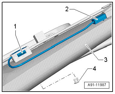
The ANC microphones are located inside the headliner.
Overview - ANC Microphones. Refer to → Chapter "Component Location Overview - ANC Microphones".
Removing
- Turn off the ignition and all electrical consumers and remove the ignition key.
It is necessary to lower the headliner on each side in order to remove the ANC microphones.
- Lower the headliner. Refer to → Body Interior; Rep. Gr.70; Roof Trim Panels; Headliner, Removing and Installing.
- Disconnect the connector -2- from each microphone.
- Pry the microphone -1- out of the retainer and then remove it from the headliner -3-.
The cover -4- remains inside the headliner.
Installing
- Install in reverse order of removal.