Audi A6 Typ 4G: Repair Information
Shock Absorber Leaks
Shock absorbers are frequently rejected and exchanged because of leaks. Examinations on the test stand and on the vehicle have shown that the replacement of a large number of rejected shock absorbers was not justified.
Slight leaking of oil ("sweating") at piston rod seal is no reason to replace a shock absorber. A shock absorber damp with oil is OK under the following circumstances:
 Note
Note
Minor oil excretion is advantageous since piston rod oil seal gets lubricated, which increases service life. This is true for front and rear shock absorbers.
- Oil leakage (shaded in illustration -arrow-) is visible, but dull, matte and possibly dry due to dust.
- One-sided oil or dirt film formation, no dripping.
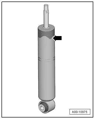
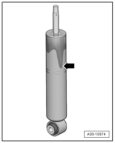
A shock absorber is not OK under the following circumstances:
- Dripping -arrow-, completely coated with oil film
- A wet oil film that runs down indicates a leaky shock absorber. A replacement is required.
Shock Absorbers, Checking when Removed
Defective shock absorbers are noticeable when driving due to loud rumbling noises - a result of wheel hopping - especially on poor stretches of road. Moreover, they can be recognized by a large loss of oil.
Note
Shock absorbers are maintenance-free, shock absorber oil cannot be topped off.
A removed shock absorber can be checked by hand as follows:
- Press together shock absorber by hand.
- Piston rods must move smoothly and with uniform difficulty over the entire range
- Release the piston rod.
- On shock absorbers with sufficient gas pressure, piston rods return to initial position by themselves.
Note
- If this is not the case, shock absorber must be replaced. As long as oil loss is not large, the effectiveness represents that of a conventional shock absorber.
- The damping function is also completely available without gas pressure, as long as there is no large loss of oil. However, noise may increase.
Shock Absorbers, Checking on Shock Tester
Shock absorbers can be checked while installed using the shock tester (shock absorber testing device). The damping effect can be evaluated based on the dial reading or print-out.
Special tools and workshop equipment required
- Maha Shock Absorber Tester -VAS1990-
Test Prerequisites
- Temperature +10 through +40 ºC (50 ºF through 104 ºF).
- Driver in vehicle.
- Tire pressure OK.
- Drive vehicle straight onto center of wheel contact plates.
- Front wheels in straight position.
- Electromechanical parking brake loosened, foot brake not actuated.
Threshold
Shock absorber condition can only be judged as follows:
- Sufficient damping effect
or
- Insufficient damping effect
Note
- Intermediate values for reduced damping performance cannot be read out.
- A prognosis on service life is not permitted.
- Measured values that occur with the involvement of the suspension travel end stops are incorrect.
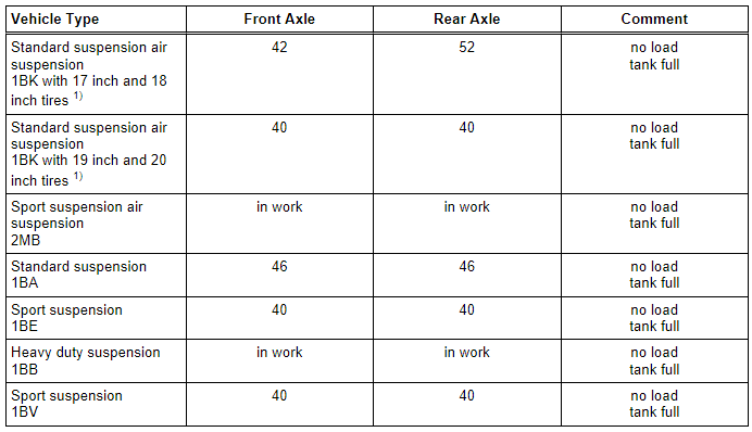
The following values apply only to the test stands named above. If the specified values are exceeded, the shock absorber action has weakened enough that a replacement is recommended.
Example:
Threshold = 70
- -a- = greater than 70: Insufficient damping effect
- -a- = less than 70: Sufficient damping effect
The shock absorber combination installed in the vehicle is indicated by the corresponding PR number on the vehicle data plate.
Explanation of weight and production relevant numbers (PR no.). Refer to → Chapter "Production Control Number (PR number) Explanation".
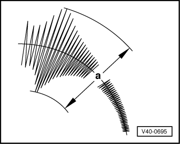
Threshold "a" in mm
Note
- If the readout value is greater than the limit value "a" (table value): Damping effect insufficient, see replace shock absorber.
- If the readout value is less than the limit value "a" (table value): Damping effect sufficient ⇒ Shock absorber does not need to be replaced.
Sportback
1) The vehicle is set to "standard vehicle height"; it is not permitted to perform the measurement when the vehicle is set to "dynamic" and with the vehicle lifted in "highest level".
The Tires must be "Partially Loaded" when Measuring the Tire Pressure.
Clean Working Conditions
- Thoroughly clean connecting points and their surrounding areas before loosening.
- When installing steering gear, make sure centering sleeves are correctly seated between console and steering gear.
- Place removed parts on a clean surface and cover them so that they do not get dirty. Use foil and paper. Only use lint-free cloths!
- Only install clean components: Remove the replacement parts from their packaging just prior to installing them.
- Use exclusively lubricants and sealants marked with part numbers.
- Carefully cover or seal open components, if repairs are not carried out immediately.
General Information
 Caution
Risk of damaging the threads in the vehicle body.
- The bolts and nuts at all suspension parts must not be loosened or tightened with an impact wrench.
- Always install the bolts and nuts by hand for the first few turns.
- When installing waxed components, contact surfaces must be cleaned. Contact surfaces must be free of wax and grease.
- Tightening specifications for non-lubricated bolts and nuts are given.
- Always replace self-locking nuts and bolts.
- Always replace the bolts and nuts, which are tightened with an additional tightening angle.
- Welding or straightening operations are not permitted on load-bearing or wheel-controlling components.
- Always avoid the following actions with coil springs: Striking with a hammer, welding beads, applying color identification later.
- Do not perform any welding or grinding (separating work) in coil spring or suspension strut area! Cover coil spring or suspension struts if necessary.
- When loosening, removing or installing hydraulic, pneumatic or electrical line, always make a sketch or take a picture. This ensures installation is the same as the original.
- If the cable ties, brackets or mounting elements were removed during the repair procedure, they must be installed at their original location.
- Lightly coat the splines on the outer joint with assembly paste before installing the outer joint into the wheel hub. Refer to the Parts Catalog.
- Never allow the drive axle just to hang loose under the vehicle or to bend them at the joints.
- Vehicles without a drive axle must not be moved, otherwise the wheel bearing will be damaged. If a vehicle must be moved, be sure to note the following:
- Install an outer joint in place of the drive axle.
- Tighten the outer joint to 200 Nm.
- Bonded rubber bushings have a limited range of motion. For this reason only tighten threaded connections at control arms if vehicle is in curb weight position. Refer to → Chapter "Wheel Bearing in Control Position, Lifting Vehicles with Air Suspension".
- Always replace bonded rubber bushings on both sides of vehicle.
- If the vehicle must still have an axle alignment, only tighten the bolts and nuts that were loosened when making adjustments to the tightening specification. Tighten the bolts and nuts to the specified additional tightening angle after the alignment/adjustment is complete.
 WARNING
There is the risk of an accident.
If vehicle will be driving on the streets, all bolts and nuts must be tightened properly!
General Repair Information
A number of generally applicable instructions for individual repair operations, which are otherwise mentioned at various points in the Shop Manual, are summarized here. They apply to this repair manual.
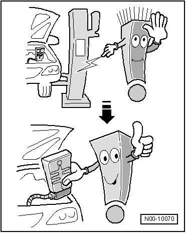
- Before performing repairs on the electromechanical steering gear, determine the cause of the damage as accurately as possible using the Vehicle Diagnostic Tester in the "Guided Fault Finding", "Vehicle Self-Diagnosis" and "Measurement" modes.
Contact Corrosion
Contact corrosion can occur if incorrect fasteners (bolts, nuts, washers, etc.) are used.
For this reason, only fastening elements with a special surface coating (Dacromet) are installed. Allocation. Refer to the Parts Catalog.
In addition, rubber and plastic parts and adhesive are of non-conducting materials.
If there are doubts as to whether parts should be reinstalled, install new parts.
Note
- Only use genuine Audi replacement parts. They have been checked and are compatible with aluminum.
- Accessories must be approved by Audi AG!
- Damage due to contract corrosion is not covered under warranty!
Steering Gear
To perform a problem-free and successful steering gear repair, extreme caution and cleanliness, as well as properly functioning tools are an important requirement. The usual basic safety precautions also, naturally apply when carrying out vehicle repairs.
Seals, Sealing Rings
- Always replace seals and gaskets.
- After removing seals, inspect contact surface on housings and shafts for burrs and damage and repair if necessary.
- Remove all residual sealant of fluid seals from sealing surfaces, no sealant residue must enter the steering gear housing when doing this.
Bolts and Nuts
- Loosen and tighten the bolt and nut from the covers and housings diagonally.
- Do not cant but loosen and tighten especially sensitive parts in diagonal manner in stages, for example servo motor with control module.
- Tightening specifications for non-lubricated bolts and nuts are given.
- Always replace self-locking nuts and bolts.
- Always replace the bolts and nuts, which are tightened with an additional tightening angle.
Electrical Components
Surely everyone has been shocked at one time or another when coming into contact with a metal object. The reason for this is the build-up of static electricity in the human body. This charge can lead to functional problems by touching the electrical components of steering gear.
- Touch a grounded object, such as, a water pipe or a vehicle hoist, before working on electrical components. Do not make direct contact on connector terminals.
Wheel Bearing in Curb Weight, Lifting Vehicles with Coil Spring
Special tools and workshop equipment required
- Engine and Gearbox Jack -VAS6931-
- Tensioning Strap -T10038-
- Engine/Gearbox Jack Adapter - Wheel Hub Support -T10149-
Note
All bolts at suspension parts with bonded rubber bushings must always be tightened in curb weight position (unloaded condition).
Bonded rubber bushings have a limited range of motion.
Axle components with bonded rubber bushings must be brought into the position they will be in during driving before tightening (curb weight position).
Otherwise, the bonded rubber bushing will be stressed resulting in a shortened service life.
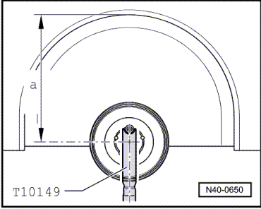
By raising appropriate suspension using Engine and Gearbox Jack -VAS6931- and Engine/Gearbox Jack Adapter - Wheel Hub Support -T10149-, this position can be simulated on the hoist.
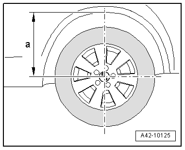
- Measure dimension -a- from the center of the wheel to the lower edge of the wheel housing before beginning work, for example, using a tape measure.
The Measurement must be taken with the Vehicle in Curb Weight Position (No Load).
- Note the measurement. It will be required for tightening bolts/nuts.
Front Axle
Before appropriate suspension is raised, vehicle must be strapped to lift arms of hoist using Tensioning Strap -T10038-.
Rear Axle
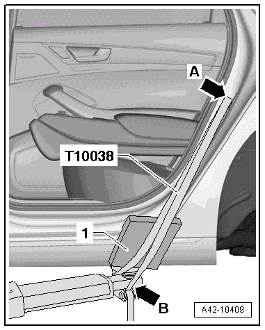
Before lifting the suspension, the vehicle must secured to the lifting arms on the hoist -arrow B- using the Tensioning Strap -T10038- over the striker pin -arrow A-.
- Place a piece of foam rubber -1- between the sill panel and the Tensioning Strap -T10038- and then tension the Tensioning Strap -T10038-.
Note
Be careful not to scratch the sill panel.
Caution
The vehicle could fall off the hoist if it is not secured.
- Remove the wheel. Refer to → Chapter "Wheels and Tires".
- Turn the wheel hub until one of the holes for the wheel bolts is on top.
- Install Engine/Gearbox Jack Adapter - Wheel Hub Support -T10149- with wheel bolt on wheel hub.
Tightening of the respective bolts/nuts must only occur if dimension -a-, measured before installation between wheel hub center and lower edge of wheel house, has been attained.
- Lift the wheel bearing housing using the Engine and Gearbox Jack -VAS6931- until the dimension -a- is reached.
WARNING
- Do not lift or lower vehicle with the engine and gearbox jack still under the vehicle.
- Do not leave the Engine and Gearbox Jack -VAS6931- under the vehicle any longer than necessary.
- Tighten the bolts and nuts.
- Lower the wheel bearing housing.
- Move Engine and Gearbox Jack -VAS6931- away from under vehicle.
- Remove the Engine/Gearbox Jack Adapter - Wheel Hub Support -T10149-
Wheel Bearing in Control Position, Lifting Vehicles with Air Suspension
Special tools and workshop equipment required
- Engine and Gearbox Jack -VAS6931-
- Engine/Gearbox Jack Adapter - Wheel Hub Support -T10149-
- Vehicle Diagnostic Tester
Note
All chassis component bolts with bonded rubber bushings must be tightened with the control position.
Bonded rubber bushings have a limited range of motion.
Before axle components with bonded rubber bushings are tightened, they have to be brought to a position which matches the position when the vehicle is being operated (control position).
Otherwise the rubber mounting will be stressed, resulting in a reduced service life.
By raising appropriate suspension using Engine and Gearbox Jack -VAS6931- and Engine/Gearbox Jack Adapter - Wheel Hub Support -T10149-, this position can be simulated on the hoist.
Front Axle
- Engine must be installed.
Rear Axle
Before lifting the suspension, the vehicle must secured to the lifting arms on the hoist -arrow B- using the Tensioning Strap -T10038- over the striker pin -arrow A-.
- Place a piece of foam rubber -1- between the sill panel and the Tensioning Strap -T10038- and then tension the Tensioning Strap -T10038-.
Note
Be careful not to scratch the sill panel.
Caution
The vehicle could fall off the hoist if it is not secured.
- Place vehicle on hoist. Refer to → Chapter "Raising and Lowering with Open and Closed Air Suspension System".
- Remove the air suspension system. Refer to → Chapter "System, Venting or Filling".
- Remove the wheel. Refer to → Chapter "Wheels and Tires".
- Turn the wheel hub until one of the holes for the wheel bolts is on top.
- Install Engine/Gearbox Jack Adapter - Wheel Hub Support -T10149- with wheel bolt.
- Insert Engine/Gearbox Jack Adapter - Wheel Hub Support -T10149- into Engine and Gearbox Jack -VAS6931- and press wheel bearing housing far enough upward until control position, dimension -a-, is obtained.
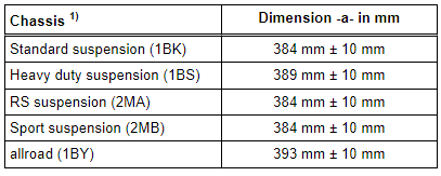
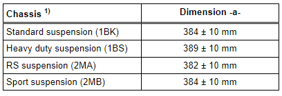
Dimension -a- is dependent on standing height of installed suspension:
Sportback Front Axle
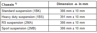
Sedan/Avant Front Axle
Sportback Rear Axle
Sedan/Avant Rear Axle
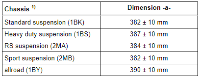
1) The suspension that the vehicle is equipped with is indicated on the vehicle data plate. The suspension is indicated by a PR number. For the correct PR numbers and assigned suspensions. Refer to → Chapter "Production Control Number (PR number) Explanation".
- Lift the wheel bearing housing using the Engine and Gearbox Jack -VAS6931- until the dimension -a- is reached.
WARNING
- Do not lift or lower the vehicle when the Engine and Gearbox Jack -VAS6931- is below the vehicle.
- Do not leave the Engine and Gearbox Jack -VAS6931- under the vehicle any longer than necessary.
Working After Adjusting Control Position
- Tighten the bolts and nuts.
- Lower the wheel bearing housing.
- Remove the Engine and Gearbox Jack -VAS6931- from under the vehicle.
- Remove Engine/Gearbox Jack Adapter - Wheel Hub Support -T10149-.
- Install the wheel and tighten. Refer to → Chapter "Wheels and Tires".
- Fill the air suspension system. Refer to → Chapter "System, Venting or Filling".
WARNING
All bolts and nuts must be tightened properly before driving the vehicle!
Raising and Lowering with Open and Closed Air Suspension System
Raising with Air Suspension System Not Open
- If the clearance for the hoist arms is insufficient, send the vehicle to "lift" (highest level) before lifting the vehicle on the shop hoist and turn on the "changing a wheel mode". Refer to the Owner's Manual.
This ensures that the hoist arms can pivot under the vehicle and the air suspension system will not make any unintended adjustments.
- Position hoist lifting arms under intended lift points on longitudinal members and raise vehicle.
Lowering with Air Suspension System Not Closed
- Lower hoist and place vehicle on wheels.
- Swing back hoist lifting arms.
- Switch off the "Changing a Wheel mode" and select a driving mode. Refer to the Owner's Manual.
Note
"Changing a wheel mode" is automatically deactivated when the vehicle speed exceeds 10 km/h.
Lifting with the Air Suspension System Opened
- If the vehicle was lifted with the air suspension system open, then read the points in the sequence specified in "lowering with the air suspension system opened" before lowering the vehicle back onto it wheels.
Lowering with Open Air Suspension System
- Connect all air lines to their corresponding components.
- Make sure the air suspension on the rear axle is locked correctly to the wheel bearing housing. Refer to → Fig. "Air Spring Installed Position".
- Make sure the air suspension on the rear axle is inserted into the hole in the body with the centering pin. Refer to → Fig. "Air Spring Installed Position".
- Fill the system. Refer to → Chapter "System, Venting or Filling".
- Lower the vehicle onto its wheels.
- Turn off the "changing a wheel mode". Refer to the Owner's Manual.
Note
"Changing a wheel mode" is automatically deactivated when the vehicle speed exceeds 10 km/h.
