Audi A6 Typ 4G: Shift Lock Solenoid -N110-, Removing and Installing
Removing
- Move the selector lever into "P".
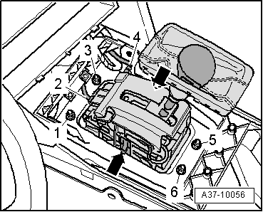
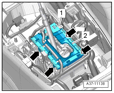
- Loosen the nuts -1, 3, 5 and 6- a few turns but do not remove them completely.
 Note
Note
- This lowers the shift mechanism function unit slightly for better accessibility.
- Ignore -2 and 4- and -arrow-.
 Caution
The shift mechanism can be destroyed by broken clips, tabs or other objects.
Make sure no components or other objects fall into the shift mechanism. The shift mechanism must be replaced if that happens.
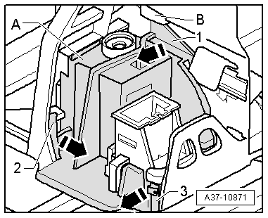
- Open the retaining tabs -2- and -3- in the direction of the -arrow-, slightly raise the front of the sealing cap -A- and hold it in that position.
Note
This prevents the retaining tabs from engaging again.
- Open the upper tab -1- in direction of -arrow- above the bracket -B- and remove the cap -A-.
- Disconnect the connector on the Shift Lock Solenoid -N110-.
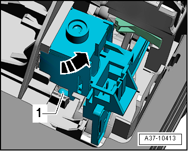
- Push the hook -A- in direction of -arrow- and hold it in this position.
Note
Replace the selector mechanism function unit if any of the hooks -A- are broken off.
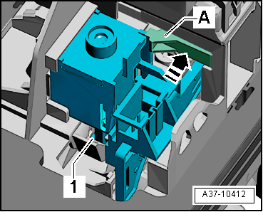
- Tilt the Shift Lock Solenoid -N110- in the direction of the -arrow- so that the ball rod -1- comes out of the lever on the selector mechanism.
- Remove the Shift Lock Solenoid -N110-.
Installing
Install in reverse order of removal. Note the following:
- Turn the ball rod -1- into the correct installed position.
- Install the Shift Lock Solenoid -N110- at an angle into the selector mechanism and then tilt it opposite the direction of -arrow-.
- The ball rod -1- must engage completely in the operating lever on shift mechanism. Press it down using a small screwdriver if necessary.
- Attach the Shift Lock Solenoid -N110- to the hook -A-.
- Position the cover -A- over the Shift Lock Solenoid -N110- and carefully lock it in -1 through 3-.
- Connect the electrical connectors.
- Check the shift mechanism function before completing assembly, refer to → Chapter "Gearshift Mechanism, Checking".
Selector Lever Sensor System Control Module -J587-, Removing and Installing
Removing
- Remove the selector lever handle, refer to → Chapter "Selector Lever Handle, Removing and Installing".
- Remove the Multimedia System Control Head -E380-, refer to → Communication; Rep. Gr.91; Infotainment System; Multimedia System Control Head E380, Removing and Installing.
- Disconnect the connector -1-.
- Open the four tabs-arrows- and remove the Selector Lever Sensor System Control Module -J587--item 2- upward.
Installing
Install in reverse order of removal. Note the following:
- Let the Selector Lever Sensor System Control Module -J587- latch with the four tabs.
- Install the Multimedia System Control Head -E380-, refer to → Communication; Rep. Gr.91; Infotainment System; Multimedia System Control Head E380, Removing and Installing.
- Install the selector lever handle, refer to → Chapter "Selector Lever Handle, Removing and Installing".
Transmission Park Selector Switch -F305-, Removing and Installing
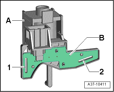
- Component location: The Transmission Park Selector Switch -F305-, which consists of two microswitches -1- and -2-, is installed on the circuit board -B- on the Shift Lock Solenoid -N110--A-.
The Transmission Park Selector Switch -F305- can only be replaced together with the Shift Lock Solenoid -N110-.
Removing and installing, refer to → Chapter "Shift Lock Solenoid -N110-, Removing and Installing".
Selector Shaft Seal, Replacing
Special tools and workshop equipment required
- Pry lever -80-200-
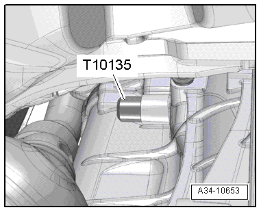
- Seal Installer - Selector Shaft -T10135-
Procedure
Vehicles with a 8-cylinder gasoline engine:
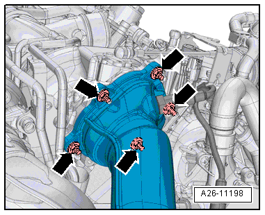
- Remove the catalytic converters, refer to → Engine Mechanical, Fuel Injection and Ignition; Rep. Gr.26; Emissions Control; Catalytic Converter, Removing and Installing.
Vehicles with a 6-cylinder TDI engine:
- Remove the particulate filter, refer to → Engine Mechanical, Fuel Injection and Glow Plug; Rep. Gr.26; Emissions Control; Particulate Filter, Removing and Installing.
All vehicles:
- Remove the plenum chamber bulkhead, refer to → Body Exterior; Rep. Gr.50; Bulkhead; Overview - Bulkhead.
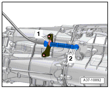
- Remove the selector lever cable ball socket -2- using the Pry Lever - 80-200- from the gearshift lever.
Note
Do not bend or kink the selector lever cable.
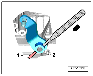
- Remove the spring pin -1- from the selector lever -2--arrow-.
- Remove the selector lever from the selector shaft.
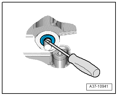
Caution
The selector shaft running surface could get damaged.
Position the screwdriver.
- Pierce shaft seal with a small screwdriver and pull out.
- Apply ATF to the circumference and the space between the sealing lips of the new shaft seal.
- Installed position: Open side of shaft seal faces transmission.
- Slide the shaft seal onto the selector shaft.
- Install the shaft seal all the way in using the Seal Installer - Selector Shaft -T10135-. Do not tilt it while installing.
- Install the spring pin on the selector shaft lever while it is still removed.
- Slide the gearshift lever onto the gearshift shaft and install the spring pin.
- Install the plenum chamber bulkhead, refer to → Body Exterior; Rep. Gr.50; Bulkhead; Overview - Bulkhead.
- Install the catalytic converter or the particulate filter, refer to → Rep. Gr.26; Exhaust Pipes/Mufflers; Overview - Muffler.