Audi A6 Typ 4G: Transmission, Removing
Transmission, Removing, Vehicles with 6-Cylinder Gasoline Engine
Special tools and workshop equipment required
- Pry lever -80-200-
- Engine and Gearbox Jack -VAS6931-
- Tensioning Strap -T10038-
- Motor Transport Loop -T40016-
- Crankshaft Socket -T40058-
- Gearbox Support -T40173-
- M8 x 20 bolt
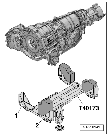
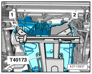
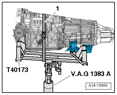
Preparing the Gearbox Support -T40173-:
- The bracket attached to -item 1- must be removed.
- The bracket -item 2- must be turned so that the longer side faces up as illustrated.
Removing
- Position the front wheels so they are straight.
- Turn off the ignition and remove the key.
 Caution
Risk of damaging electronic components when disconnecting the battery.
Complete the steps for disconnecting the battery.
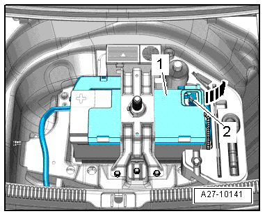
- Disconnect the battery ground cable -2-, refer to → Electrical Equipment; Rep. Gr.27; Battery; Battery, Disconnecting and Connecting.
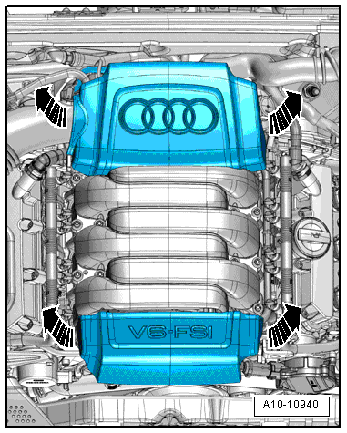
Vehicles with FSI engines:
- Remove the engine cover upward -arrows-.
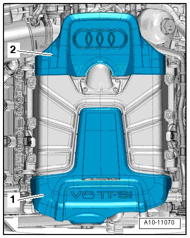
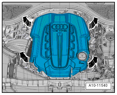
Vehicles with a TFSI engine:
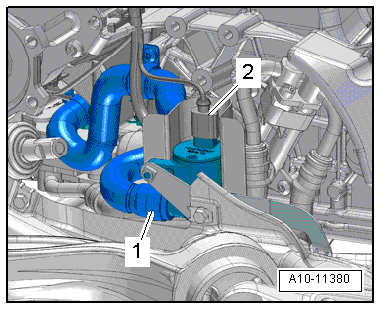
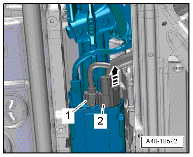
- Remove the engine covers -1- and -2- upward.
All vehicles:
- Remove the front wheels, refer to → Suspension, Wheels, Steering; Rep. Gr.44; Wheels and Tires.
- Remove left and right drive axle cover -1- in the wheel housing, refer to → Body Exterior; Rep. Gr.66; Noise Insulation; Overview - Noise Insulation.
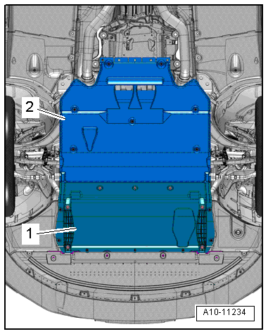
- Remove the noise insulations -1- and -2-, refer to → Body Exterior; Rep. Gr.66; Noise Insulation; Noise Insulation, Removing and Installing.
- Remove the left and right front muffler, refer to → Rep. Gr.26; Exhaust Pipes/Mufflers; Overview - Muffler.
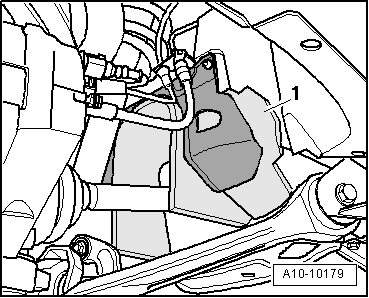
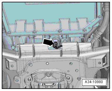
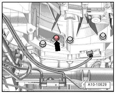
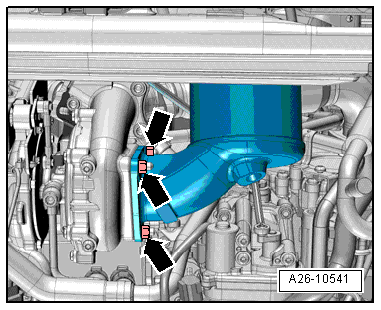
- Remove the bolt -2-.
- Press the tab -1- in direction of -arrow B- and swivel it toward the rear -arrow A-.
- Remove the plenum chamber bulkhead, refer to → Body Exterior; Rep. Gr.50; Bulkhead; Overview - Bulkhead.
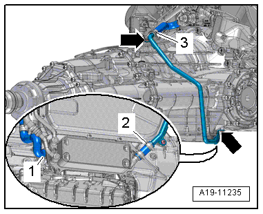
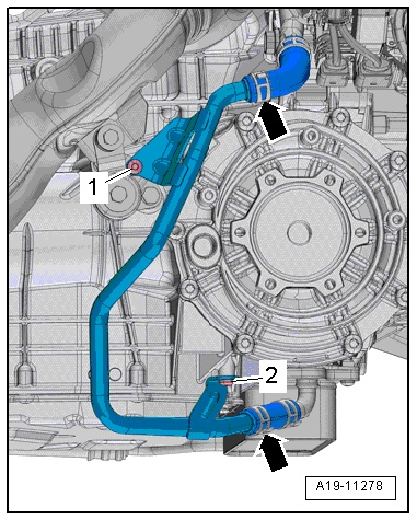
- Remove the right coolant pipe on the transmission, refer to → Rep. Gr.19; Coolant Pipes; Coolant Pipes, Removing and Installing.
Vehicles with FSI engines:
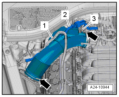
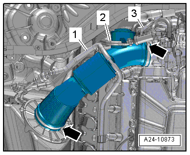
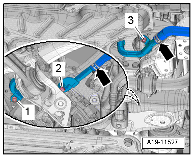
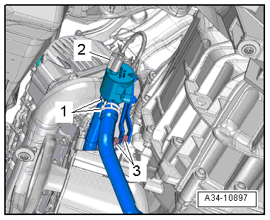
- Free up the fuel hose -1- and the hose -2- for the EVAP canister from the air guide pipe.
- Remove the vacuum hose -3- from the connection on the air guide pipe.
- Loosen the clamps -arrows- and remove the air guide pipe.
- Move the tower brace into its installed position and then tighten the bolts hand-tight.
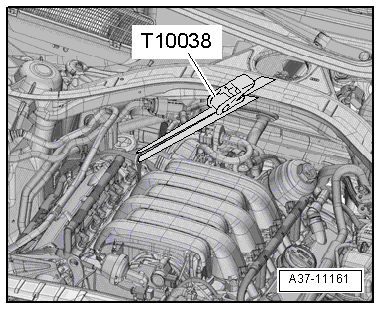
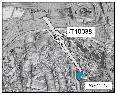
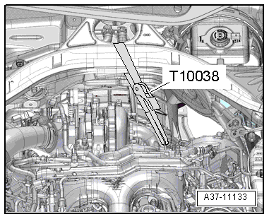
- Secure the engine with the Tensioning Strap -T10038- as illustrated.
Vehicles with a TFSI engine:
- Free up the fuel hose -1- and the hose -2- for the EVAP canister from the air guide pipe.
- Remove the vacuum hose -3- from the connection on the air guide pipe.
- Loosen the clamps -arrows- and remove the air guide pipe.
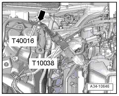
- Tighten the Motor Transport Loop -T40016- with an M8 x 20 bolt-arrow- in the threaded hole for the tower brace.
- Install the Tensioning Strap -T10038- as illustrated.
All vehicles:
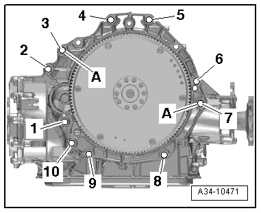
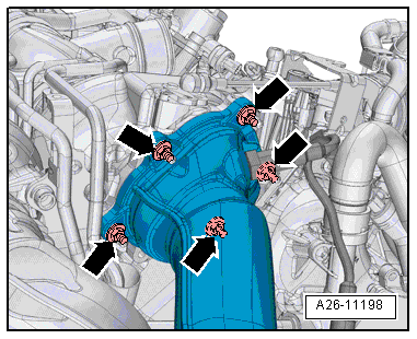
- Remove the bolts -2 through 5- connecting the engine to transmission. They are accessible from above.
 Note
Note
Ignore -item A-.
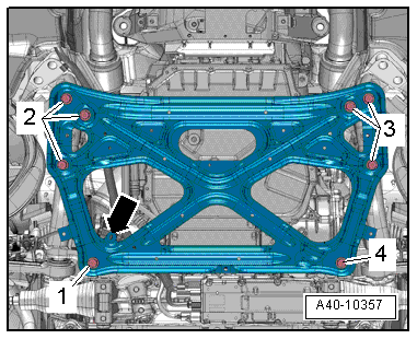
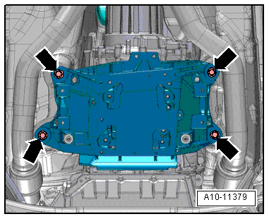
- Remove the subframe crossbrace, refer to → Suspension, Wheels, Steering; Rep. Gr.40; Subframe; Subframe Crossbrace, Removing and Installing.
Caution
The suspension components could be damaged.
Do not rest the vehicle on its wheels if the subframe mount, the steering gear or the subframe crossbrace are not installed correctly.
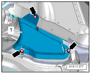
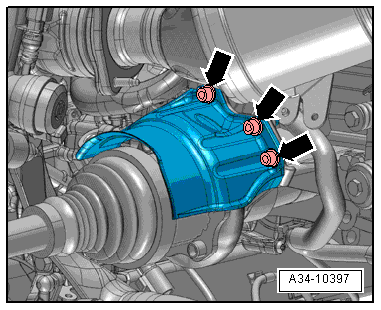
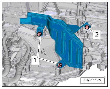
- Remove the bolts -arrows- and remove the left heat shield -1-.
- Remove the bolts -arrows- and then remove the heat shield from the right drive axle.
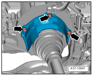
- Remove the bolts -arrows- and the left drive axle heat shield.
- Remove the left and right drive axles from the transmission flange shafts, refer to → Suspension, Wheels, Steering; Rep. Gr.40; Drive Axle; Drive Axle, Removing and Installing.
- Remove the driveshaft, refer to → Rep. Gr.39; Removal and Installation.
Caution
There is a risk of destroying the transmission control module (Mechatronic) with static discharge.
- Always "discharge" the static electricity before working with electric connectors. Do this by touching a grounded object, for example vehicle ground, the vehicle or the hoist.
- Do not touch contacts in transmission connector with hands.
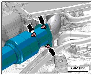
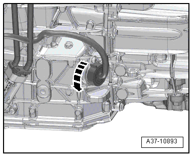
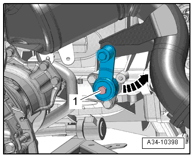
- Turn the twist lock counter-clockwise -arrow- and disconnect the connector from the transmission.
- Disconnect the connector -arrow- for the Transmission Fluid Temperature Sensor 2 -G754-.
- Remove the steering intermediate shaft from the steering gear and the push the splines together, refer to → Suspension, Wheels, Steering; Rep. Gr.48; Steering Column; Steering Intermediate Shaft, Removing and Installing.
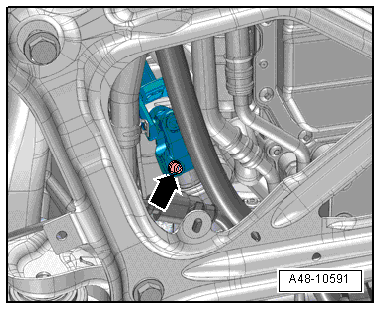
- Remove the bolt -1- press the retaining tab off the transmission and tilt it back -arrow-.
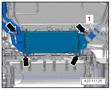
- Remove the bolts -arrows- and press the ATF cooler to the side.
Note
Ignore -item 1-.
- Loosen the clamp -1- and remove the coolant hose.
Note
Ignore -item 2-.
- Slide the retainer toward the rear -arrow- and press down the release in order to disconnect the connector -2- for the steering gear.
- Disconnect the connector -1-.
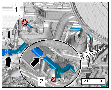
- Remove the bolts -1, 2- from the lower left coolant pipe.
Note
Ignore -arrows-.
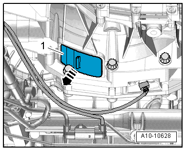
- Remove the lower cover -1- from the transmission -arrow-.
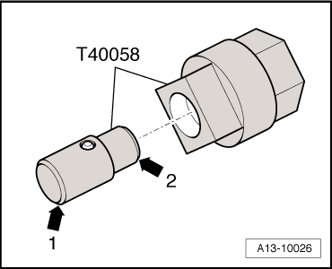
- Insert the adapter -T40058- guide pins as follows:
- The large diameter -arrow 1- faces the engine.
- The small diameter -arrow 2- faces the adapter.
Vehicles with FSI engines:
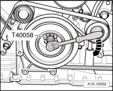
- Counterhold the crankshaft with the Crankshaft Socket -T40058- and an angled wrench and loosen the drive plate bolts.
Note
When mounting, turn the crankshaft only in the direction of engine rotation -arrow-.
Vehicles with a TFSI engine:
- Counterhold the crankshaft with the Crankshaft Socket -T40058- and an angled wrench and loosen the drive plate bolts.
Note
When mounting, turn the crankshaft only in the direction of engine rotation -arrow-.
All vehicles:
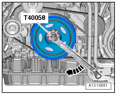
- Remove the 6 drive plate bolts -arrow- while turning the crankshaft 60º further in the direction of engine rotation.
- Remove the starter bolt -1-.
- Remove the starter from the transmission and leave it in the installation position.
- Remove remaining transmission to engine connecting bolts -6 through 10-.
Note
Ignore -item A-.
Caution
Danger of leaks in the ATF pan.
The Gearbox Support -T40173- must not be set on the ATF pan.
- Place the Engine and Gearbox Jack -VAS6031- with the prepared Gearbox Support -T40173- on the bottom of the transmission.
The transmission support must be placed at the front as follows:
- The bracket -2- fits into the flywheel on the transmission housing on the left side of the transmission.
- The transmission mount is positioned on the differential housing on the right side of the transmission. Insert a flat piece of rubber -1- in between to protect the housing.
- Secure the transmission with a tensioning strap -1-.
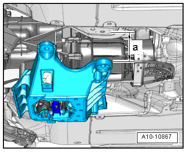
- Remove the bolts from the tunnel crossmember -arrows-.
Note
The illustration id shown without the Engine and Gearbox Jack -VAS6931-.
- Lower the tunnel crossmember to the dimension -a- using the Engine and Gearbox Jack -VAS6931-.
- Dimension -a- = maximum 100 mm.
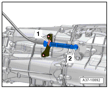
- Remove the selector lever cable ball socket -2- using the Pry Lever - 80-200- from the gearshift lever.
- Remove the circlip -1- and free up the selector lever cable.
Note
Do not bend or kink the selector lever cable.
- Lightly preload the Tensioning Strap -T10038-.
- Press the transmission off the engine and lower it carefully using the Engine and Gearbox Jack -VAS6931-.
Transmission, Removing, Vehicles with 8-Cylinder Gasoline Engine
Special tools and workshop equipment required
- Pry lever -80-200-
- Engine and Gearbox Jack -VAS6931-
- Tensioning Strap -T10038-
- Gearbox Support -T40173-
- Crankshaft Turning Tool -T40272-
- M8 x 20 bolt
Preparing the Gearbox Support -T40173-:
- The bracket attached to -item 1- must be removed.
- The bracket -item 2- must be turned so that the longer side faces up as illustrated.
Removing
- Position the front wheels so they are straight.
- Turn off the ignition and remove the key.
Caution
Risk of damaging electronic components when disconnecting the battery.
Complete the steps for disconnecting the battery.
- Disconnect the battery ground cable -2-, refer to → Electrical Equipment; Rep. Gr.27; Battery; Battery, Disconnecting and Connecting.
- Remove the engine cover -arrows-.
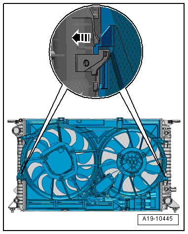
- Remove the fan shroud, refer to → Rep. Gr.19; Radiator/Coolant Fan; Fan Shroud, Removing and Installing.
- Remove the front wheels, refer to → Suspension, Wheels, Steering; Rep. Gr.44; Wheels and Tires.
- Remove left and right drive axle cover -1- in the wheel housing, refer to → Body Exterior; Rep. Gr.66; Noise Insulation; Overview - Noise Insulation.
- Remove the noise insulations -1- and -2-, refer to → Body Exterior; Rep. Gr.66; Noise Insulation; Noise Insulation, Removing and Installing.
- Remove the catalytic converters, refer to → Rep. Gr.26; Emissions Control; Catalytic Converter, Removing and Installing.
- Remove the right coolant pipe on the transmission, refer to → Rep. Gr.19; Coolant Pipes; Coolant Pipes, Removing and Installing.
- Remove the bolts -2 through 5- connecting the engine to transmission. They are accessible from above.
Note
Ignore -item A-.
- Move the tower brace into its installed position and then tighten the bolts hand-tight.
- Secure the engine with the Tensioning Strap -T10038- as illustrated.
- Remove the subframe crossbrace, refer to → Suspension, Wheels, Steering; Rep. Gr.40; Subframe; Subframe Crossbrace, Removing and Installing.
Caution
The suspension components could be damaged.
Do not rest the vehicle on its wheels if the subframe mount, the steering gear or the subframe crossbrace are not installed correctly.
- Remove the bolts -arrows- and remove the left heat shield -1-.
- Remove the bolts -arrows- and then remove the heat shield from the right drive axle.
- Remove the bolts -arrows- and the left drive axle heat shield.
- Remove the left and right drive axles from the transmission flange shafts, refer to → Suspension, Wheels, Steering; Rep. Gr.40; Drive Axle; Drive Axle, Removing and Installing.
- Remove the driveshaft, refer to → Rep. Gr.39; Removal and Installation.
- Remove the nuts -1- and bolt -2- and then remove the heat shield.
Caution
There is a risk of destroying the transmission control module (Mechatronic) with static discharge.
- Always "discharge" the static electricity before working with electric connectors. Do this by touching a grounded object, for example vehicle ground, the vehicle or the hoist.
- Do not touch contacts in transmission connector with hands.
- Turn the twist lock counter-clockwise -arrow- and disconnect the connector from the transmission.
- Free up the wiring harness on the transmission.
- Disconnect the connector -arrow- for the Transmission Fluid Temperature Sensor 2 -G754-.
- Remove the steering intermediate shaft from the steering gear and the push the splines together, refer to → Suspension, Wheels, Steering; Rep. Gr.48; Steering Column; Steering Intermediate Shaft, Removing and Installing.
- Remove the bolts -arrows- and press the ATF cooler to the side.
Note
Ignore -item 1-.
- Loosen the clamp -1- and remove the coolant hose.
Note
Ignore -item 2-.
- Loosen the retainer -arrow-, push the release downward and disconnect the connector -2- from the Power Steering Control Module -J500-.
- Disconnect the connector -1- from the Power Steering Control Module -J500-.
- Remove the bolts -1, 2, 3- from the lower left coolant pipe.
Note
Ignore -arrows-.
- Remove the lower cover -1- from the transmission -arrow-.
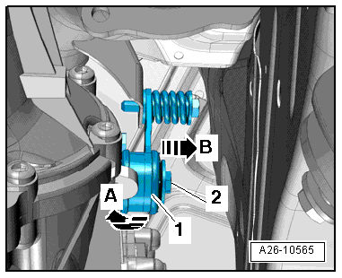
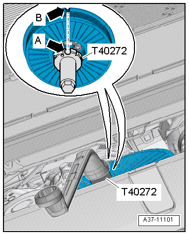
- Attach the Crankshaft Turning Tool -T40272- to the vibration damper bolts.
- The semi-round recess -arrow A- on the Crankshaft Turning Tool -T40272- must face the semi-round recess -arrow B- on the vibration damper.
Note
Ignore the notch on the Crankshaft Turning Tool -T40272-.
- Counterhold the crankshaft with the Crankshaft Turning Tool -T40272- and an angled wrench and loosen the drive plate bolts.
Note
When mounting, turn the crankshaft only in the direction of engine rotation -arrow-.
- Remove the six flywheel bolts -arrow- while turning the crankshaft 60º further in the direction of engine rotation.
- Remove the starter bolt -1-.
- Remove the starter from the transmission and leave it in the installation position.
- Remove remaining transmission to engine connecting bolts -6 through 10-.
Note
Ignore -item A-.
Caution
Danger of leaks in the ATF pan.
The Gearbox Support -T40173- must not be set on the ATF pan.
- Place the Engine and Gearbox Jack -VAS6031- with the prepared Gearbox Support -T40173- on the bottom of the transmission.
The transmission support must be placed at the front as follows:
- The bracket -2- fits into the flywheel on the transmission housing on the left side of the transmission.
- The transmission mount is positioned on the differential housing on the right side of the transmission. Insert a flat piece of rubber -1- in between to protect the housing.
- Secure the transmission with a tensioning strap -1-.
- Remove the bolts from the tunnel crossmember -arrows-.
Note
The illustration id shown without the Engine and Gearbox Jack -VAS6931-.
- Lower the tunnel crossmember to the dimension -a- using the Engine and Gearbox Jack -VAS6931-.
- Dimension -a- = maximum 100 mm.
- Remove the selector lever cable ball socket -2- using the Pry Lever - 80-200- from the gearshift lever.
- Remove the circlip -1- and free up the selector lever cable.
Note
Do not bend or kink the selector lever cable.
- Lightly preload the Tensioning Strap -T10038-.
- Press the transmission off the engine and lower it carefully using the Engine and Gearbox Jack -VAS6931-.
Transmission, Removing, 6-Cylinder TDI Engine
Special tools and workshop equipment required
- Pry lever -80-200-
- Engine and Gearbox Jack -VAS6931-
- Hose Clip Pliers -VAS6362-
- Tensioning Strap -T10038-
- Crankshaft Socket -T40058-
- Gearbox Support -T40173-
Preparing the Gearbox Support -T40173-:
- The bracket attached to -item 1- must be removed.
- The bracket -item 2- must be turned so that the longer side faces up as illustrated.
Removing
- Position the front wheels so they are straight.
- Turn off the ignition and remove the key.
Caution
Risk of damaging electronic components when disconnecting the battery.
Complete the steps for disconnecting the battery.
- Disconnect the battery ground cable -2-, refer to → Electrical Equipment; Rep. Gr.27; Battery; Battery, Disconnecting and Connecting.
- Remove the front wheels, refer to → Suspension, Wheels, Steering; Rep. Gr.44; Wheels and Tires.
- Remove left and right drive axle cover -1- in the wheel housing, refer to → Body Exterior; Rep. Gr.66; Noise Insulation; Overview - Noise Insulation.
- Remove the bolts -arrows- and remove the left heat shield -1-.
- Remove the driveshaft, refer to → Rep. Gr.39; Removal and Installation.
- Remove the noise insulations -1- and -2-, refer to → Body Exterior; Rep. Gr.66; Noise Insulation; Noise Insulation, Removing and Installing.
- Remove the particulate filter and the front exhaust pipe, refer to → Rep. Gr.26; Exhaust Pipes/Mufflers; Overview - Muffler.
- Drain the coolant, refer to → Rep. Gr.19; Cooling System/Coolant; Coolant, Draining and Filling.
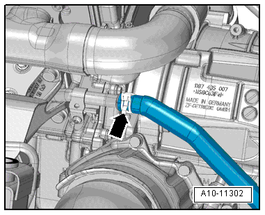
- Loosen the clamp -arrow- and remove the coolant hose from the left coolant pipe.
- Remove the bolts -2 through 5- connecting the engine to transmission. They are accessible from above.
Note
Ignore -item A-.
- Move the tower brace into its installed position and then tighten the bolts hand-tight.
- Secure the engine with the Tensioning Strap -T10038- as illustrated.
- Remove the bolts -arrows- and then remove the heat shield from the right drive axle.
- Remove the left and right drive axles from the transmission flange shafts, refer to → Suspension, Wheels, Steering; Rep. Gr.40; Drive Axle; Drive Axle, Removing and Installing.
Caution
There is a risk of destroying the transmission control module (Mechatronic) with static discharge.
- Always "discharge" the static electricity before working with electric connectors. Do this by touching a grounded object, for example vehicle ground, the vehicle or the hoist.
- Do not touch contacts in transmission connector with hands.
- Turn the twist lock counter-clockwise -arrow- and disconnect the connector from the transmission.
- Disconnect the connector -arrow- for the Transmission Fluid Temperature Sensor 2 -G754-.
- Remove the steering intermediate shaft from the steering gear and the push the splines together, refer to → Suspension, Wheels, Steering; Rep. Gr.48; Steering Column; Steering Intermediate Shaft, Removing and Installing.
- Remove the subframe crossbrace, refer to → Suspension, Wheels, Steering; Rep. Gr.40; Subframe; Subframe Crossbrace, Removing and Installing.
Caution
The suspension components could be damaged.
Do not rest the vehicle on its wheels if the subframe mount, the steering gear or the subframe crossbrace are not installed correctly.
- Slide the retainer toward the rear -arrow- and press down the release in order to disconnect the connector -2- for the steering gear.
- Disconnect the connector -1-.
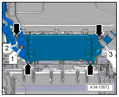
- Remove the bolts -arrows- and press the ATF cooler to the side.
Note
Ignore -items 1, 2 and 3-.
- Remove the lower cover -1- from the transmission -arrow-.
- Insert the adapter -T40058- guide pins as follows:
- The large diameter -arrow 1- faces the engine.
- The small diameter -arrow 2- faces the adapter.
- Counterhold the crankshaft with the Crankshaft Socket -T40058- and an angled wrench and loosen the drive plate bolts.
Note
When mounting, turn the crankshaft only in the direction of engine rotation -arrow-.
- Remove the 6 drive plate bolts -arrow- while turning the crankshaft 60º further in the direction of engine rotation.
- Disconnect the connector -2-.
- Remove the bolt -3- and move the Transmission Fluid Cooling Valve -N509- to the side.
Note
Ignore -item 1-.
- Remove the starter bolt -1-.
- Remove the starter from the transmission and leave it in the installation position.
Note
For the bolt -7-there is a nut with anti-twist mechanism on the engine-side
- Remove remaining transmission to engine connecting bolts -6 through 10-.
Note
Ignore -item A-.
Caution
Danger of leaks in the ATF pan.
The Gearbox Support -T40173- must not be set on the ATF pan.
- Place the Engine and Gearbox Jack -VAS6031- with the prepared Gearbox Support -T40173- on the bottom of the transmission.
The transmission support must be placed at the front as follows:
- The bracket -2- fits into the flywheel on the transmission housing on the left side of the transmission.
- The transmission mount is positioned on the differential housing on the right side of the transmission. Insert a flat piece of rubber -1- in between to protect the housing.
- Secure the transmission with a tensioning strap -1-.
- Remove the bolts from the tunnel crossmember -arrows-.
Note
The illustration id shown without the Engine and Gearbox Jack -VAS6931-.
- Lower the tunnel crossmember to the dimension -a- using the Engine and Gearbox Jack -VAS6931-.
- Dimension -a- = maximum 100 mm.
- Remove the selector lever cable ball socket -2- using the Pry Lever - 80-200- from the gearshift lever.
- Remove the circlip -1- and free up the selector lever cable.
Note
Do not bend or kink the selector lever cable.
- Lightly preload the Tensioning Strap -T10038-.
- Press the transmission off the engine and lower it carefully using the Engine and Gearbox Jack -VAS6931-.
