Audi A6 Typ 4G: Transmission, Installing
Special tools and workshop equipment required
- Torque Wrench 1332 Insert - Ring Wrench - 16mm -VAG1332/14-
- Clutch Module Assembly Aid -T40169-
- Clutch Module Transportation Lock -T40170-
Transmission installation tightening specifications, refer to → Chapter "Transmission Tightening Specifications"
Procedure
 Note
Note
- Replace the bolts that were tightened with an additional turn.
- Replace self-locking nuts and bolts and seals, gaskets and o-rings.
- The hose connections as well as the air guide pipes and hoses must be free of oil and grease before installing.
- Secure all hose connections with hose clamps of the same type as those equipped by the factory, refer to the Parts Catalog.
- To secure the air guide hoses on their connections, spray the clamps used previously with rust remover before installing.
- When installing, bring all cable ties back to same positions.
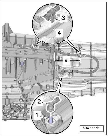
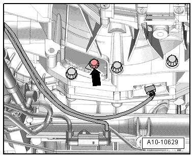
Check that the bleeder hose is installed correctly for vehicles with 6-cylinder engines:
- The elbow of the bleeder hose -2- must be pressed onto the connection -1-.
- Press on the loose elbow until it audibly engages.
- Check that the base for both of the clamps -3- are correctly seated on the housing ribs -4-:
- The distance -a- from the rear clamp base to the housing flange must be 130 mm.
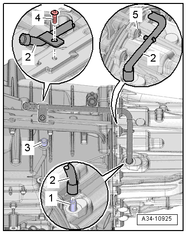
Check that the bleed pipe is installed correctly for vehicles with 8-cylinder engines:
- The elbow of the bleeder pipe -2- must be pressed onto the connection -1-.
- Press on the loose elbow until it audibly engages.
- The bleed pipe retaining pin must connect in the bolt head -5-.
- The bolt -4- must be tightened to 10 Nm.
- The ATF breather pipe -3- must remain open.
All vehicles:
- Clean the ATF pipe and the ATF cooler after replacing the transmission or after repairing the transmission.
- Always clean the threaded holes for the engine/transmission bolts in the cylinder block before assembling the transmission using a thread cutter.
 Caution
Danger of leaks in the ATF pan.
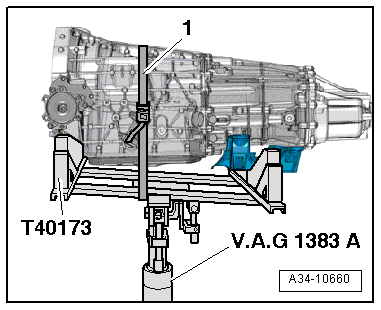
The Gearbox Support -T40173- must not be set on the ATF pan.
- Mount the transmission onto the Gearbox Support -T40173- and secure it using the tension strap -1- as illustrated.
- The following preparations must be made before connecting the engine and transmission:
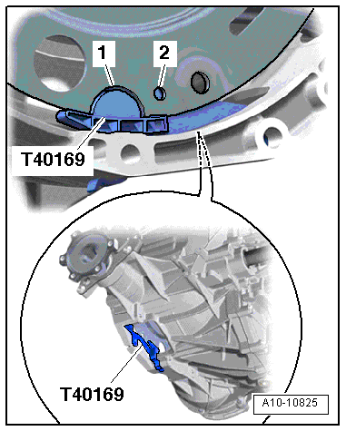
- Insert the Clutch Module Assembly Aid -T40169- in the transmission housing and the flywheel from below as shown in the illustration.
- The assembly tool must engage in the semi-circular opening -1- and into the check hole -2-.
Note
There is only 1 inspection opening on the circumference. Rotate the flywheel as needed.
- Install the bolts from the assembly device into the holes on the transmission housing.
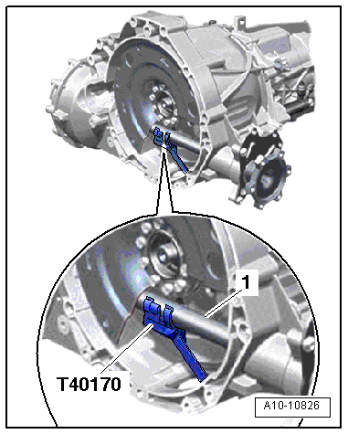
- Insert the Clutch Module Transportation Lock -T40170- in the transmission housing from below and secure it on the flange shaft -1-.
- Inspect the aluminum bolts used to connect the engine to the transmission to see if they can be used again and mark them, if necessary.
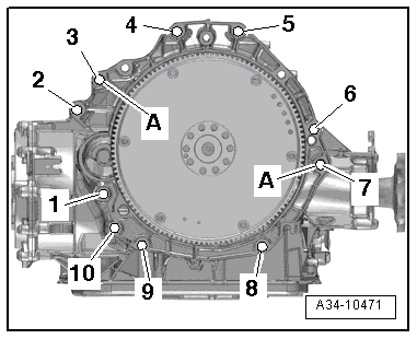
- Check if the alignment sleeves -A- for centering the engine/transmission are in the cylinder block and insert them if they are not.
- Connect the transmission to the engine and then tighten the engine/transmission connecting bolts -6- and -7-.
- Install the tunnel crossmember, refer to → Chapter "Overview - Subframe Mount".
Note
The illustration id shown without the Engine and Gearbox Jack -VAS6931-.
- Lower the Engine and Gearbox Jack -VAS6931- with the Gearbox Support -T40173- and set aside.
- Tighten then engine bolts to the transmission accessible from underneath.
- Remove the Clutch Module Transportation Lock -T40170- and the Clutch Module Assembly Aid -T40169-.
Note
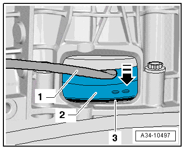
The following step is necessary to make sure the clutch module rests on the drive plate evenly and is not tilted.
- Push the flywheel slightly against the drive plate -3--arrow--2- using a pry bar -1-.
Note
Use the Torque Wrench 1331 Insert - Open Jaw - 13mm -VAG1332/14- to tighten the bolts.
- Tighten the flywheel to the drive plate as follows:
- Install the first bolt -arrow- and tighten by hand (2 Nm).
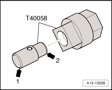
Vehicles with 6-cylinder gasoline or 6-cylinder TDI engine:
- Insert the adapter -T40058- guide pins as follows:
- The large diameter -arrow 1- faces the engine.
- The small diameter -arrow 2- faces the adapter.
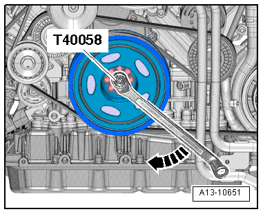
- Continue turning the crankshaft on the vibration damper 180º in the direction of the engine rotation using the Crankshaft Socket -T40058--arrow-.
Note
The 6-cylinder TFSI gasoline engine is shown in the illustration.
- Tighten the bolt with the crankshaft in this position, refer to → Chapter "Overview - Flywheel and Dual Clutch".
- Continue turning the crankshaft 60º and tighten the remaining 5 bolts to the tightening specification, refer to → Chapter "Overview - Flywheel and Dual Clutch".
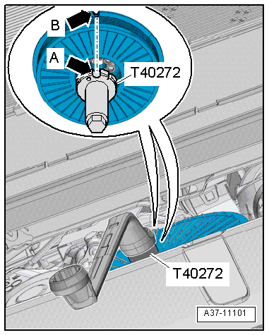
Vehicles with a 8-cylinder gasoline engine:
- Attach the Crankshaft Turning Tool -T40272- to the vibration damper bolts.
- The semi-round recess -arrow A- on the Crankshaft Turning Tool -T40272- must face the semi-round recess -arrow B- on the vibration damper.
Note
Ignore the notch on the Crankshaft Turning Tool -T40272-.
- Turn the crankshaft at the vibration damper 180º further in the direction of the engine rotation -arrow- with Crankshaft Turning Tool -T40272- and the offset open-end wrench.
- Tighten the bolt with the crankshaft in this position, refer to → Chapter "Overview - Flywheel and Dual Clutch".
- Continue turning the crankshaft 60º and tighten the remaining 5 bolts to the tightening specification, refer to → Chapter "Overview - Flywheel and Dual Clutch".
All vehicles:
Install in reverse order of removal. Note the following:
- Install selector lever cable, refer to → Chapter "Selector Lever Cable, Removing and Installing".
- Install the starter, refer to → Electrical Equipment; Rep. Gr.27; Starter; Starter, Removing and Installing.
- Tighten the remaining engine/transmission connecting bolts -3 through 5-.
- Install the Transmission Fluid Cooling Valve -N509-, refer to → Rep. Gr.19; Coolant Pump/Thermostat; Coolant Valve, Removing and Installing.
- Install the coolant pipe, refer to → Rep. Gr.19; Coolant Pipes; Coolant Pipes, Removing and Installing.
- Installing the ATF cooler, refer to → Chapter "Overview - ATF Circuit".
- Attach the steering intermediate shaft to the steering gear, refer to → Suspension, Wheels, Steering; Rep. Gr.48; Steering Column; Steering Intermediate Shaft, Removing and Installing.
- Connections and routing, refer to → Wiring diagrams, Troubleshooting & Component locations.
- Install the driveshaft, refer to → Rep. Gr.39; Removal and Installation.
- Installing the drive axle and drive axle heat shield, refer to → Suspension, Wheels, Steering; Rep. Gr.40; Drive Axle; Overview - Drive Axle.
- Install the subframe heat shield, refer to → Body Exterior; Rep. Gr.66; Molding/Trim/Extensions/Trim Panels; Overview - Heat Shield.
- Install the subframe crossbrace, refer to → Suspension, Wheels, Steering; Rep. Gr.40; Subframe; Overview - Subframe.
- Install the fan shroud, refer to → Rep. Gr.19; Radiator/Coolant Fan; Fan Shroud, Removing and Installing.
- Fill the engine coolant, refer to → Rep. Gr.19; Cooling System/Coolant; Coolant, Draining and Filling.
- Install the plenum chamber bulkhead, refer to → Body Exterior; Rep. Gr.50; Bulkhead; Overview - Bulkhead.
- Install the exhaust system, refer to → Rep. Gr.26; Exhaust Pipes/Mufflers; Overview - Muffler.
- Install the drive axle covers and noise insulation, refer to → Body Exterior; Rep. Gr.66; Noise Insulation; Overview - Noise Insulation.
- Install the front wheels, refer to → Suspension, Wheels, Steering; Rep. Gr.44; Wheels and Tires.
- Observe measures after connecting the battery, refer to → Electrical Equipment; Rep. Gr.27; Battery; Battery, Disconnecting and Connecting.
Caution
Danger of causing damage to the control modules due to the excess voltage.
Do not use a charger to jump start!
- Check and adjust the selector lever cable, refer to → Chapter "Selector Lever Cable, Checking and Adjusting".
- Check the ATF level and correct if necessary, refer to → Chapter "ATF Level, Checking".
- Check transmission fluid level and fill, refer to → Chapter "Transmission Fluid Level, Checking".
Transmission Tightening Specifications
Note
- The tightening specifications apply only to lightly greased, oiled, phosphated or blackened nuts and bolts.
- Additional lubricants, such as engine oil or transmission fluid are permissible, but lubricants containing graphite are not.
- Do not use any ungreased parts.
- Tightening specification tolerance +- 15%.
.png)
S tronic transmission on the 6-cylinder or 8-cylinder gasoline engine
.png)
1) Mount the auxiliary adapter
2) Bolt strength rating 10.9. There is no limit to the number of times steel bolts may be used.
3) The bolts may be used two times.
S tronic transmission on 6-cylinder TDI engine
.png)
1) Mount the auxiliary adapter
2) Bolt strength rating 10.9. There is no limit to the number of times steel bolts may be used.
3) The bolts may be used two times.
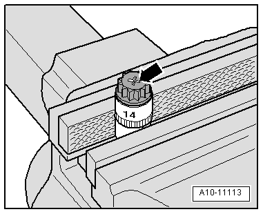
- The aluminum bolts -2 through 10- can be used twice. Therefore, the bolts must be marked with two notches "X" made by a chisel after they have be used the first time -arrow-.
- To prevent damaging the bolts when marking them, do not clamp them in a vise. Insert the bolt using a 14 mm socket with a 1/2 drive, which is inserted in to the vise, as illustrated.
- Bolts marked with an "X" may not be used again.