Audi A6 Typ 4G: Spring, Removing and Installing
Spring, Removing and Installing, Coil Spring
Special tools and workshop equipment required
- Pneumatic/Hydraulic Foot Pump -VAS6179-
- Spring Tensioning System -VAS6274-
- Spring Tensioning System - Audi Set -VAS6274/10-
 WARNING
- Before removing and installing the coil spring the Spring Tensioning System -VAS6274- with the Spring Tensioning System - Audi Set -VAS6274/10- must be retrofitted.
- Retrofit the Spring Tensioning System -VAS6274- with the Spring Tensioning System - Audi Set -VAS6274/10-. Refer to → Chapter "Spring Tensioning System, Converting".
 Note
Note
The rest of the tools from the Spring Tensioning System - Audi Set -VAS6274/10- are needed later in the procedure.
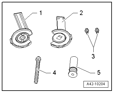
1 - Spring Tensioning System - Audi Set - Thrust Plate with Swivel Bearing - VAS6274/10-1-
2 - Spring Tensioning System - Audi Set - Thrust Plate with Securing Plate - VAS6274/10-2-
3 - Locking device Bolts
4 - Spring Tensioning System - Audi Set - Spindle - VAS6274/10-4-
5 - Sleeve
Removing
- Remove the rear wheel. Refer to → Chapter "Wheels and Tires".
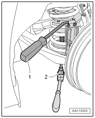
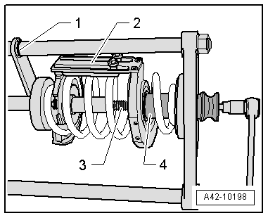
- Slide the securing lever back in direction of -arrow- if necessary.
Note
This and the following illustrations show the procedure without the stone deflector.
- Insert the new Spring Tensioning System - Audi Set - Thrust Plate with Securing Plate -VAS6274/10-2- with the locking device bracket from the supplementary seat from the outside.
1 - Spring Tensioning System - Audi Set - Thrust Plate with Securing Plate - VAS6274/10-2-
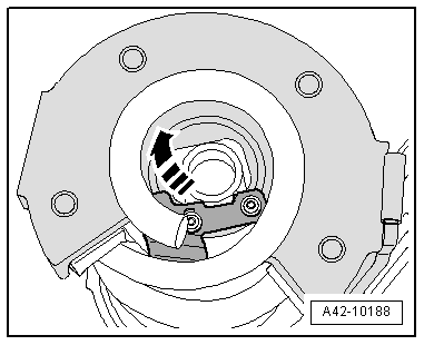
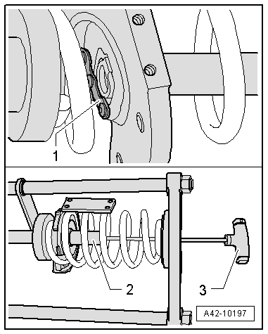
- Insert the piston -2- with the T-handle -3- in the pressure plate. Slide the locking lever on the pressure plate back toward the outside (open).
- Press the locking lever in direction of -arrow- to secure the piston.
- Rotate the Thrust Plate with Securing Plate all the way up.
- Insert the new Spring Tensioning System - Audi Set - Thrust Plate with Swivel Bearing -VAS6274/10-1- with the locking device bracket from the supplementary seat from the outside.
1 - Spring Tensioning System - Audi Set - Thrust Plate with Swivel Bearing - VAS6274/10-1-
The locking device bracket -2- must be installed in the front.
- Rotate the Thrust Plate with Swivel Bearing all the way down.
 Caution
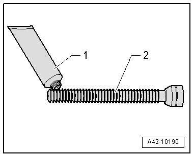
- Coat the front area of the spindle lightly with the accompanying grease before removal and installation of each spring.
- Only grease the spindle with the accompanying grease. The spindle will be damaged if a different grease is used.
- Coat the front area of the new Spring Tensioning System - Audi Set - Spindle -VAS6274/10-4- lightly with the appropriate grease.
1 - Tube of grease from the Spring Tensioning System -VAS6274- or from the Spring Tensioning System - Audi Set -VAS6274/10-
2 - Spring Tensioning System - Audi Set - Spindle - VAS6274/10-4-
- Install the new Spring Tensioning System - Audi Set - Spindle -VAS6274/10-4- hand tight with the Spring Tensioning System - Socket -VAS6274/6-.
1 - Spring Tensioning System - Audi Set - Spindle - VAS6274/10-4-
2 - Spring Tensioning System - Socket -VAS6274/6-
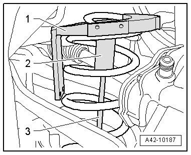
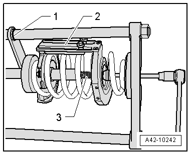
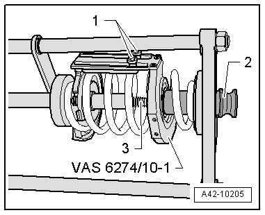
- Attach the locking devices -1 and 2- on both thrust plates to each other.
- Install the new bolts -3- by hand.
WARNING
The coil spring may only be tensioned or released if both locking device brackets -1 and 2- are connected to each other using both bolts -3-.
- Lightly tension the thrust plates using the new Spring Tensioning System - Audi Set - Spindle -VAS6274/10-4-.
- Check to see if both coil springs are seated correctly in the pressure plates.
Note
When tensioning the coil spring, the locking device bracket must face forward in the direction of travel.
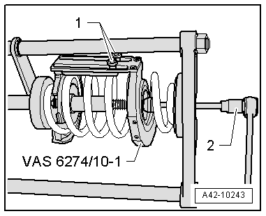
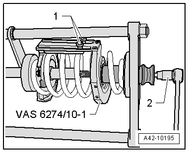
- Tension the coil spring with the Spring Tensioning System - Socket -VAS6274/6-. While doing so counterhold with the Spring Tensioning System - Counterhold Tool -VAS6274/7-.
1 - Spring Tensioning System - Counterhold Tool -VAS6274/7-
2 - Spring Tensioning System - Socket -VAS6274/6-
Caution
- Do not use an impact wrench to tighten the coil spring.
- Use a commercially available ratchet to tighten.
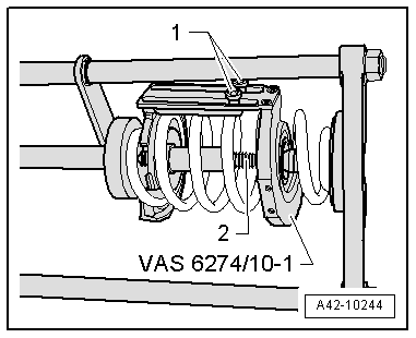
- Tighten the coil spring -1- until the stone deflector -3- and the lower spring plate -2- can be removed. Tighten the coil spring -1- further if necessary.
Caution
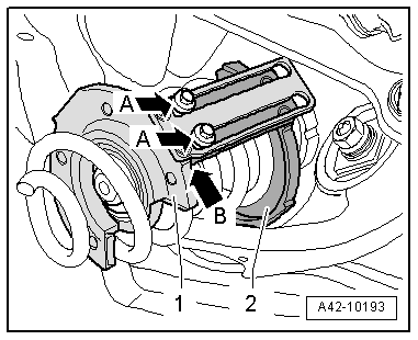
- When tightening, make sure the bolts -A arrows- do not lie on the thrust plate stop -1-.
- The thrust plate locking device -2- must not lie on the stop -arrow B- on the pressure plate -1-.
- Remove the coil spring forward and down.
Release the Tension of the Coil Spring in the Spring Tensioning System -VAS6274-.
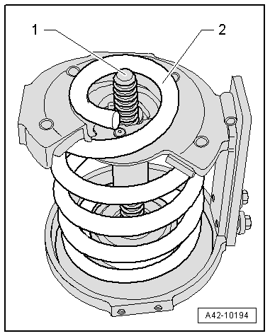
- Rotate the spindle -1- back slightly if necessary. The spindle -1- must not project over the end of the coil spring -2-.
- Insert the left coil spring on the spring plate -1- so the stop -2- aligns with the marking "L". Only applies to the left coil spring.
- For the right coil spring, the stop -2- must align with the "R" marking.
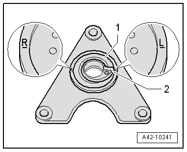
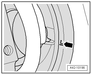
- Position the bottom side of the end of the left coil spring in the Spring Tensioning System -VAS6274- at the "L" marking -arrow-.
- Position the bottom side of the end of the right coil spring in the Spring Tensioning System -VAS6274- at the "R" marking.
- Make a marking -1- with a felt-tip marker.
Note
The marking -1- is needed when tightening for installation.
- The locking device -2- faces up.
- Tighten the bolts -1- slightly by hand.
2 - Spring Tensioning System - Socket -VAS6274/6-
- Release the coil spring tension using the Spring Tensioning System - Socket -VAS6274/6-. Release the tension at the same time using the Spring Tensioning System -VAS6274- and the Pneumatic/Hydraulic Foot Pump -VAS6179-.
- Remove the spindle -2- once the coil spring is released.
- Remove the locking device bolts -1- and the Spring Tensioning System - Audi Set - Thrust Plate with Swivel Bearing -VAS6274/10-1-.
- Slide the locking lever -1- back.
- Remove the piston -2- with the T-handle -3-.
- Release the coil spring completely.
Installing
Install in reverse order of removal. Note the following:
- Insert the bottom of the coil spring in the Spring Tensioning System -VAS6274-; installation position. Refer to → Fig. "Coil Spring Installed Position".
- Position the end of the left coil spring in the Spring Tensioning System -VAS6274- at the "L" marking -arrow-.
- Position the end of the right coil spring in the Spring Tensioning System -VAS6274- at the "R" marking.
- Insert the Spring Tensioning System - Audi Set - Thrust Plate with Securing Plate -VAS6274/10-2- and install the piston -2- with the T-handle -3-.
- Secure the piston -2- with the securing lever -1-.
- Insert the Spring Tensioning System - Audi Set - Thrust Plate with Swivel Bearing - VAS6274/10-1-.
- Install the locking device bolts -1- loosely.
- Insert the spindle -3-.
- Insert the sleeve -2- as far as the stop.
- Tighten the locking device bolts -1- lightly by hand. The locking device must face upward when tightening the coil spring.
- Tension the coil spring using the Spring Tensioning System - Socket -VAS6274/6-. At the same time tension using the Spring Tensioning System -VAS6274- and the Pneumatic/Hydraulic Foot Pump -VAS6179-.
2 - Spring Tensioning System - Socket -VAS6274/6-
Caution
- When tightening, make sure the locking mechanism bolts do not lie on the Spring Tensioning System - Audi Set - Thrust Plate with Swivel Bearing -VAS6274/10-1- stop.
- The Spring Tensioning System - Audi Set - Thrust Plate with Securing Plate -VAS6274/10-2- locking device must not lie on the Spring Tensioning System - Audi Set - Thrust Plate with Swivel Bearing -VAS6274/10-1- stop.
- Only tighten the coil spring as far as the marking -1-. The locking device -2- must face up.
- When tightening using the spindle -3-, make sure the sleeve -4- does not slip out of the Spring Tensioning System - Audi Set - Thrust Plate with Swivel Bearing -VAS6274/10-1-.
- Release the Spring Tensioning System -VAS6274- and remove the coil spring with the tensioner.
- Tension the coil spring -2- slightly using spindle -1-.
- The spindle -1- must only project far enough over the coil spring -2- that the upper spring plate can still rest completely on the coil spring.
- Position the coil spring with the lower spring plate -3- and stone chip protection -1- on the wheel bearing housing -2-; installed position. Refer to → Fig. "Lower Spring Plate Installed Position".
- Make sure the upper spring plate is installed; eccentric spring plate installed position. Refer to → Fig. "Upper Eccentric Spring Plate Installed Position". Install if necessary.
- Install the coil spring -1- in the lower spring plate -2- as far as the stop.
- Then release the coil spring.
- Install rear wheel. Refer to → Chapter "Wheels and Tires".
- To determine if an axle alignment is required, see Table. Refer to → Chapter "Evaluating Need for Axle Alignment".
The axle alignment must be performed on a VW/Audi approved alignment stand.
Spring, Removing and Installing, Air Spring
Special tools and workshop equipment required
- Torque Wrench 1331 5-50Nm -VAG1331-
- Torque Wrench 1332 40-200Nm -VAG1332-
Removing
Note
- Make sure no dirt gets into the pressure air system.
- Clean the area before removing connecting pieces for the air pipe lines or other components of the pressured air system.
- Seal off any open air lines and connections in the pressure system immediately with plugs or cover them.
- Bleed the rear axle air spring. Refer to → Chapter "System, Venting or Filling".
- Remove the wheel. Refer to → Chapter "Wheels and Tires".
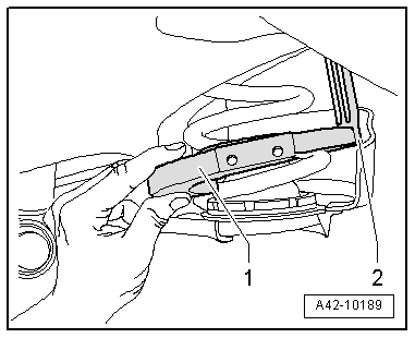
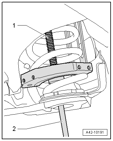
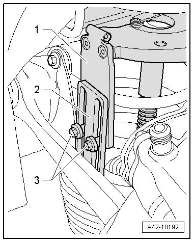
- Remove the diagonal brace, if equipped. Refer to → Chapter "Diagonal Braces, Removing and Installing".
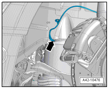
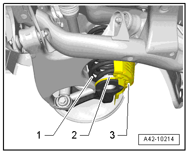
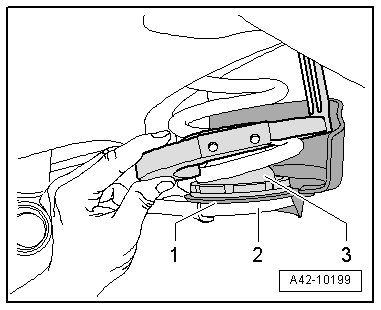
- Remove the connecting piece -arrow- from the rear air spring.
- Remove the stone chip protection -Item 3-.
- Remove the air spring downward.
Installing
Install in reverse order of removal. Note the following:
- Install the diagonal braces. Refer to → Chapter "Diagonal Braces, Removing and Installing".
- Fill the rear axle air springs. Refer to → Chapter "System, Venting or Filling".
Note
- The vehicle may be removed from the vehicle hoist only after the air springs have been filled again. Refer to → Chapter "Raising and Lowering with Open and Closed Air Suspension System".
- Make sure the positioning pin on the air spring is installed correctly inside the body before filling the air springs. The air spring must be locked secure inside the wheel bearing housing at the same time. Refer to → Fig. "Air Spring Installed Position".