Audi A6 Typ 4G: Overview - Steering Gear
Overview - Steering Gear, Steering Gear with Tie Rods
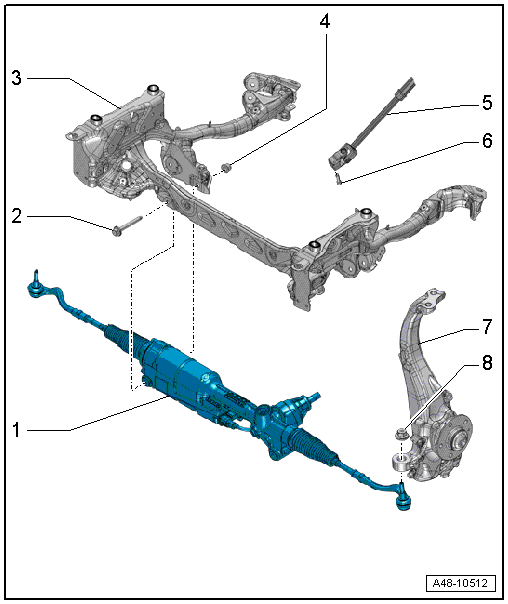
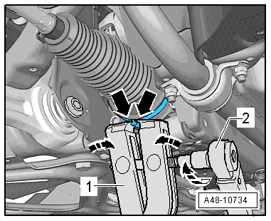
1 - Electromechanical Steering Gear with Tie Rods
- With Power Steering Control Module -J500-
- Removing and installing. Refer to → Chapter "Steering Gear, Removing and Installing".
- Servicing. Refer to → Chapter "Overview - Steering Gear".
- There are different versions. Refer to the Parts Catalog.
A removable heat shield mat was installed on the steering gear at start of production. Be sure to install this mat if installing the old steering gear again.
A removable heat shield mat on the steering gear was replaced by a bonded heat shield mat as a running change. It is therefore not necessary to take the mat from the old steering gear and installing on a new steering gear.
A replacement steering gear comes with the bonded heat shield mat.
2 - Bolt
- 80 Nm +180º turn
- Always replace if removed
3 - Subframe
4 - Nut
- Pushed into the subframe
- Always replace if removed
5 - Steering Intermediate Shaft
6 - Bolt
- Tightening specification -Item 1-
7 - Wheel Bearing Housing
8 - Nut
- 100 Nm
- Always replace if removed
Overview - Steering Gear
 Note
Note
- Always replace self-locking nuts and bolts.
- Welding or straighten work on any steering components is not permissible.
- Use only Power Steering Gear Grease to lubricate the steering rack (on the pinion side) and the ball paths (on the engine side). Note: There are different types of grease for the left and right. For allocation. Refer to the Parts Catalog.
- The clamps -1 and 8- are tensioned to different tightening specifications.
1 - Clamp
- Always replace if removed
- Use the CV Joint Boot Clamp Tool to tension the clamp.
Note
It is not permitted to open the new clamp.
- For the correct version. Refer to the Parts Catalog.
2 - Tie Rod
- 100 Nm
- Removing and installing. Refer to → Chapter "Tie Rod, Removing and Installing".
- Grease the joint with Power Steering Gear Grease
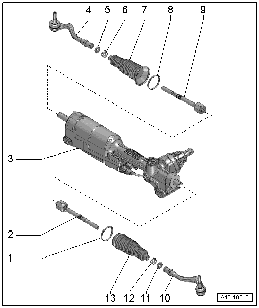
3 - Electromechanical Steering Gear
- Removing and installing. Refer to → Chapter "Steering Gear, Removing and Installing".
- Grease the steering rack with Power Steering Gear Grease Note: There are different types of grease for the left and right. For allocation. Refer to the Parts Catalog.
- There are different versions. Refer to the Parts Catalog.
A removable heat shield mat was installed on the steering gear at start of production. Be sure to install this mat if installing the old steering gear again.
A removable heat shield mat on the steering gear was replaced by a bonded heat shield mat as a running change. It is therefore not necessary to take the mat from the old steering gear and installing on a new steering gear.
A replacement steering gear comes with the bonded heat shield mat.
4 - Tie Rod End
- Removing and installing. Refer to → Chapter "Tie Rod End, Removing and Installing".
- Check dust caps for damage and correct seating
- Check dimension. Refer to → Fig. "Tie Rod End Check Dimension"
5 - Nut
- 80 Nm
- Counterhold on the tie rod end when loosening or tightening
6 - Spring Clamp
- Always replace if removed
- Spring clamp, installing.
7 - Boot
- Check for damage
- Always replace if removed
- Coat the inside of the joint boot seats all the way around and evenly with Power Steering Gear Grease before installing. Refer to the Parts Catalog.
- Check the seat for the boot on the steering gear for damage before installing. If the steering gear housing is damaged, replace the steering gear.
- Must not be twisted when toe is being adjusted
- Make sure it is installed correctly.
- Replacing. Refer to → Chapter "Boot, Removing and Installing".
8 - Clamp
- Always replace if removed
- Use the CV Joint Boot Clamp Tool to tension the clamp.
Note
It is not permitted to open the new clamp.
- For the correct version. Refer to the Parts Catalog.
9 - Tie Rod
- 100 Nm
- Removing and installing. Refer to → Chapter "Tie Rod, Removing and Installing".
- Grease the joint with Power Steering Gear Grease
10 - Tie Rod End
- Removing and installing. Refer to → Chapter "Tie Rod End, Removing and Installing".
- Check dust caps for damage and correct seating
- Check dimension. Refer to → Fig. "Tie Rod End Check Dimension"
11 - Nut
- 80 Nm
- Counterhold on the tie rod end when loosening or tightening
12 - Spring Clamp
- Always replace if removed
- Spring clamp, installing.
13 - Boot
- Check for damage
- Always replace if removed
- Coat the inside of the joint boot seats all the way around and evenly with Power Steering Gear Grease before installing. Refer to the Parts Catalog.
- Check the seat for the boot on the steering gear for damage before installing. If the steering gear housing is damaged, replace the steering gear.
- Must not be twisted when toe is being adjusted
- Make sure it is installed correctly.
- Replacing. Refer to → Chapter "Boot, Removing and Installing".
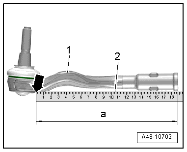
Tie Rod End Check Dimension
- Place a steel ruler -2- on the tie rod end and push it all the way up to the edge -arrow- of the tie rod end -1-.
- Replace the complete steering gear with the tie rod and tie rod end if the check dimension -a- is less than 188 mm.
Tensioning the Inner Clamp
- Mount the CV Joint Boot Clamp Tool-1- as illustrated. Make sure that the jaws of the clamp tool are seated in the corners -arrows- of the clamp.
- Tighten the clamp by turning the spindle using a torque wrench -2- (do not tilt the pliers).
- Use torque wrench -2- with 5 to 50 Nm range (for example, Torque Wrench 1331 5-50Nm -VAG1331-).
- Make sure the thread on the spindle -1- is easy to move. Lubricate with MoS2 grease, if necessary.
- If the thread is tight, for example, dirty, the required tensioning force for the hose clamp will not be achieved in spite of correct torque specification settings.
.png)
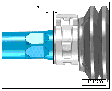
Outer Boot Assembly
- Dimension -a- 2 mm.