Audi A6 Typ 4G: Steering Column Switch Module
Overview - Steering Column Switch Module
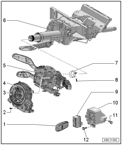
1 - Ignition Key
2 - Screw
- 0.5 Nm
3 - Transport Protection
4 - Steering Column Electronics Control Module -J527-
- With Airbag Spiral Spring/Return Spring with Slip Ring -F138-, Steering Angle Sensor -G85-
- Removing and installing. Refer to → Chapter "Steering Column Electronics Control Module -J527-, Removing and Installing".
 Caution
Risk of damaging coil connector.
Coil connector with slip ring is not to be turned following removal.
- Pin assignment for the Steering Column Electronics Control Module -J527-. Refer to → Chapter "Steering Column Electronics Control Module Connector Assignment".
5 - Mount
- With Turn Signal Switch -E2-, Windshield Wiper Intermittent Mode Switch -E22-
- On vehicles with cruise control with a Cruise control switch -E45-
- Removing and installing. Refer to → Chapter "Steering Column Combination Switch, Removing and Installing".
6 - Steering Column
7 - Clamping Ring
8 - Screw
- 6 Nm
9 - Anti-Theft Immobilizer Reader Coil -D2-
- Removing and installing. Refer to → Chapter "Anti-Theft Immobilizer Reader Coil -D2-, Removing and Installing".
10 - Mount
- For Anti-Theft Immobilizer Reader Coil -D2-
- Removing and installing. Refer to → Chapter "Anti-Theft Immobilizer Reader Coil -D2-, Removing and Installing".
11 - Screw
- 3 Nm
12 - Screw
- 3 Nm
Steering Column Switch Module, Removing and Installing
Removing
- Place the front wheels in a straight-ahead position - steering wheel in 0 position.
- Adjust steering wheel downward and to rear as far as possible, use entire adjustment range of steering column adjustment for this.
- Removing the steering wheel → Suspension, Axles, Steering; Rep. Gr.48; Steering Wheel; Steering Wheel, Removing and Installing.
- Remove the steering column trim panel. Refer to → Body Interior; Rep. Gr.68; Storage Compartments and Covers; Overview - Steering Column Trim Panel.
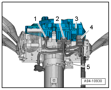
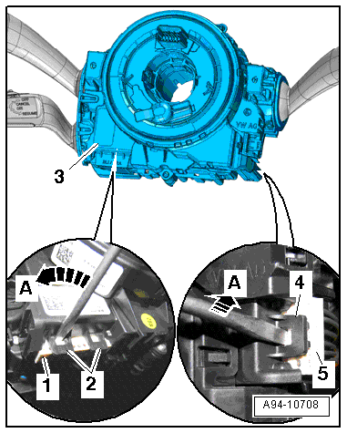
- Remove the bolt -5-.
- Disconnect the connectors -1 and 2-.
 WARNING
Before disconnecting connector -4-, discharge any electrostatic charge from your body by touching an electrically grounded vehicle component such as the door striker pin.
- Disconnect the connector -4-.
- Press catch -1- in direction of -arrow- until harness connector -2- disengages.
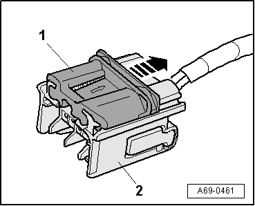
- Remove the steering column switch module -3-.
Installing
Install in reverse order of removal.
Steering Column Electronics Control Module -J527-, Removing and Installing
The Airbag Spiral Spring/Return Spring with Slip Ring -J527- and the Steering Angle Sensor -F138- are integrated in the Steering Column Electronics Control Module -G85-.
- If the control module was replaced, select the "Replace" function for the respective control module in "Guided Fault Finding" or "Guided Functions" using the Vehicle Diagnostic Tester.
Removing
- Place the front wheels in a straight-ahead position - steering wheel in 0 position.
- Adjust steering wheel downward and to rear as far as possible, use entire adjustment range of steering column adjustment for this.
- Removing the steering wheel → Suspension, Axles, Steering; Rep. Gr.48; Steering Wheel; Steering Wheel, Removing and Installing.
- Remove the steering column trim panel. Refer to → Body Interior; Rep. Gr.68; Storage Compartments and Covers; Overview - Steering Column Trim Panel.
- Remove the bolt -1-.
- Release the retaining hooks -arrows- carefully and remove the Airbag Spiral Spring/Return Spring with Slip Ring -F138--item 2- from the steering column switch module -3-.
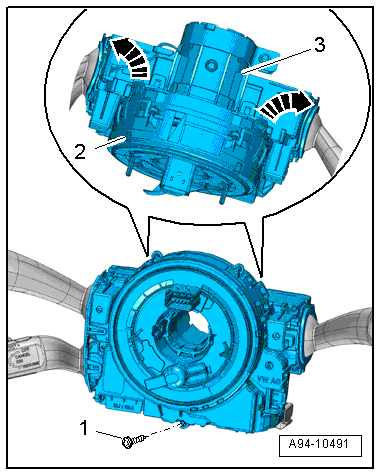
- Release the electrical connectors on the Airbag Spiral Spring/Return Spring with Slip Ring -F138--item 3- by positioning the screwdriver at the retaining hooks -2- and -4- as illustrated and carefully releasing the connectors -1- and -5- in the direction of -arrow A-.
- Remove the Airbag Spiral Spring/Return Spring with Slip Ring -F138- on the steering column switch module.
Installing
Install in reverse order of removal. Note the following:
- Make sure all retaining hooks and connectors are engaged securely.
- The steering angle sensor must be adapted in "Guided Fault Finding" or "Guided Functions" after replacing the return spring with slip ring using the Vehicle Diagnostic Tester.
Steering Column Combination Switch, Removing and Installing
 Note
Note
The Turn Signal Switch -E2-/Cruise Control Switch -E45-/Windshield Wiper Intermittent Mode Switch -E22- is integrated in the steering column combination switch.
Removing
- Remove the steering column switch module. Refer to → Chapter "Steering Column Switch Module, Removing and Installing".
- Remove the Steering Column Electronics Control Module -J527-. Refer to → Chapter "Steering Column Electronics Control Module -J527-, Removing and Installing".
- Remove the Turn Signal Switch -E2-, Cruise Control Switch -E45-, and Windshield Wiper Intermittent Mode Switch -E22-.
Installing
Install in reverse order of removal.
Steering Column Electronics Control Module Connector Assignment
- The Steering Column Electronics Control Module -J527- is part of the complete system "steering column switch module". and receives signals from steering column switch, for example.
- Check the Steering Column Electronics Control Module -J527- in the "Guided Fault Finding" mode using the Vehicle Diagnostic Tester.
Rear Side
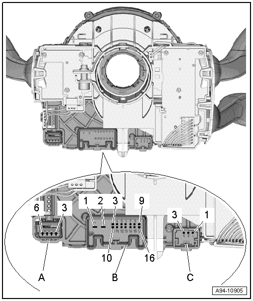
A - Airbag Control Module Connector Mount
3 - Driver Airbag Igniter -N95-"+"
4 - Driver Airbag Igniter -N95-"-"
5 - Driver Airbag Release Valve Igniter -N490-"-"
6 - Driver Airbag Release Valve Igniter -N490-"+"
B - Vehicle Electrical System Connector Mount
1 - Terminal 31/steering wheel heating
2 - Terminal 30/steering wheel heating
3 - Power supply terminal 30
4 - Not assigned
5 - Cruise control latched Off
6 - Not assigned
7 - Alarm
8 - Comfort CAN bus Low
9 - Comfort CAN bus High
10 - Power supply terminal 31
11 - Powertrain CAN bus High
12 - Powertrain CAN bus Low
13 - Signal, electric ignition switch, terminal 15
14 - Not used
15 - Not used
16 - Not used
C - Vehicle Electrical System Connector Mount
1 - Steering wheel heating button
2 - Not assigned
3 - Not assigned
