Audi A6 Typ 4G: Tie Rod, Removing and Installing
Special tools and workshop equipment required
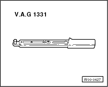
- Torque Wrench 1331 5-50Nm -VAG1331-
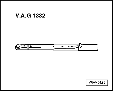
- Torque Wrench 1332 40-200Nm -VAG1332-
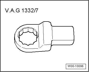
- Torque Wrench 1332 Insert - Ring Wrench - 21mm -VAG1332/7-
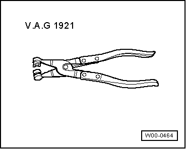
- Hose Clip Pliers -VAG1921-
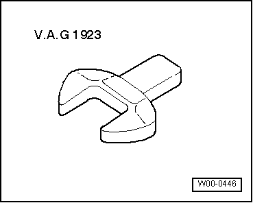
- Torque Wrench Insert - Open Jaw -VAG1923-
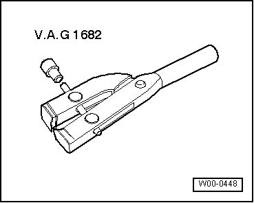
- Clamping Pliers -VAG1682A- with Clamping Pliers - Jaws -VAG1682A/1-
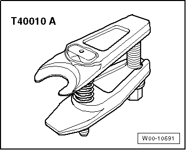
- Puller - Ball Joint -T40010A-
Removing
The tie rods can be removed and installed with the steering gear in the vehicle.
- Remove the front wheel. Refer to → Chapter "Wheels and Tires".
- Remove the noise insulation. Refer to → Body Exterior; Rep. Gr.66; Noise Insulation; Noise Insulation, Removing and Installing.
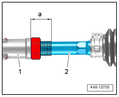
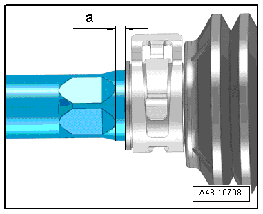
- Measure the dimension -a- between the tie rod head -1- and the left and right tie rod -2- and make a note of the value. Dimension -a- must be the same on the left and right sides after installing.
- If necessary, shorten the "longer" tie rod head (installed it deeper into the tie rod).
- Clean the power steering gear and subframe in the boot area.
 Caution
Dirt must not enter the power steering gear and boot when replacing the tie rod.
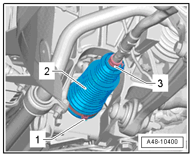
- Open the spring clamp -3- with the Hose Clip Pliers -VAG1921- and remove it.
- Remove the clamp -1- and remove the boot -2- from the power steering gear.
- Remove the nut -1- from the tie rod end joint pin -2- until it is flush with the joint pin threads. Counterhold when loosening.
To Protect Thread, Screw Nut on Pin A Few Turns.
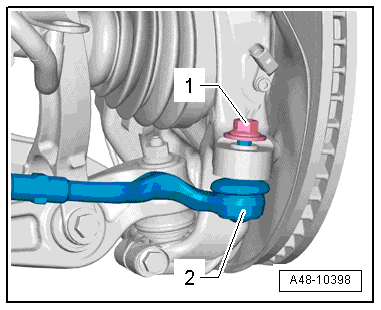
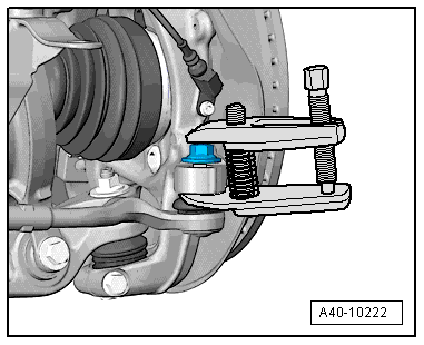
- Remove the tie rod end from the wheel bearing housing using the Puller - Ball Joint -T40010A-. Remove the nut.
 Note
Note
Make sure that both puller lever arms are parallel to each other when using greatest force, adjust if necessary.
- Remove tie rod. Counterhold at the power steering gear coupling rod with an open end wrench -1-.
2 - Torque Wrench Insert - Open Jaw -VAG1923-
Installing
Install in reverse order of removal. Note the following:
Replace the boot each time it is removed.
Coat the inside of slits in the boot all the way around and evenly with power steering gear grease before installing. Refer to the Parts Catalog.
Check the seat for the boot on the steering gear for damage before installing. If the steering gear housing is damaged, replace the steering gear.
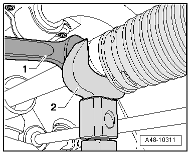
- Attach the tie rod using the Torque Wrench Insert - Open Jaw -VAG1923--2-. Counterhold at the power steering gear coupling rod with an open end wrench -1-.
- Replace the spring clamp -3- and the clamp -1-.
Clamping Sleeves, Installing:
- Install a new clamp -1- and tension it.
Boot Assembly
- Dimension -a- 2 mm.
- Align tie rod so that tie rod ball joint pints are in installation location.
- Insert the tie rod into the wheel bearing housing as far as the stop.
- Install the front wheel. Refer to → Chapter "Wheels and Tires".
- To determine if an axle alignment is required, see Table. Refer to → Chapter "Evaluating Need for Axle Alignment".
The axle alignment must be performed on a VW/Audi approved alignment stand.
Tie Rod End, Removing and Installing
Special tools and workshop equipment required
- Torque Wrench 1331 5-50Nm -VAG1331-
- Torque Wrench 1332 40-200Nm -VAG1332-
- Torque Wrench 1332 Insert - Ring Wrench - 21mm -VAG1332/7-
- Puller - Ball Joint -T40010A-
Removing
- Remove the front wheel. Refer to → Chapter "Wheels and Tires".
- Measure the dimension -a- between the tie rod head -1- and the left and right tie rod -2- and make a note of the value. Dimension -a- must be the same on the left and right sides after installing.
- If necessary, shorten the "longer" tie rod head (installed it deeper into the tie rod).
- Remove the nut -1- from the tie rod end joint pin -2- until it is flush with the joint pin threads. Counterhold when loosening.
Note
To protect thread, screw nut on pin a few turns.
- Remove the tie rod end from the wheel bearing housing using the Puller - Ball Joint -T40010A-. Remove the nut.
Note
Make sure that both puller lever arms are parallel to each other when using greatest force, adjust if necessary.
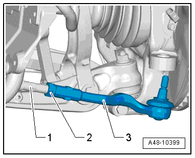
- Loosen the nut -2-. Counterhold the tie rod end -3-.
- Remove the tie rod end -3-.
Installing
Install in reverse order of removal. Note the following:
- Mount the tie rod head -1- on the tie rod -2- until dimension -a-, which was measured during removal, is reached.
- Align the tie rod head -1- so that the pin is in the installation position.
- Insert the tie rod end into the wheel bearing housing as far as the stop.
- Tighten the nut -1-. Counterhold when tightening.
- Tighten the nut -2-.
- Install the front wheel. Refer to → Chapter "Wheels and Tires".
- Axle alignment. Refer to → Chapter "Evaluating Need for Axle Alignment".
The axle alignment must be performed on a VW/Audi approved alignment stand.
Special Tools
Special tools and workshop equipment required
- Puller - Ball Joint -T40010A-
- Torque Wrench 1331 5-50Nm -VAG1331-
- Torque Wrench 1332 40-200Nm -VAG1332-
- Torque Wrench 1332 Insert - Ring Wrench - 21mm -VAG1332/7-
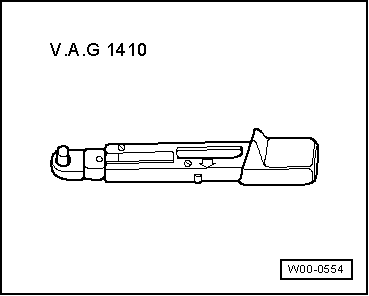
- Torque Wrench 1410 -VAG1410-
- Clamping Pliers -VAG1682A- with Clamping Pliers - Jaws -VAG1682A/1-
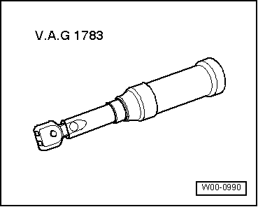
- Torque Wrench 1783 - 2-10Nm -VAG1783-
- Hose Clip Pliers -VAG1921-
- Torque Wrench Insert - Open Jaw -VAG1923-
- Steering Wheel Scales -VAS6458-