Audi A6 Typ 4G: Subframe Front Bearing, Replacing, Vehicles with AWD
Special tools and workshop equipment required
- Subframe Bushing Tool Kit -3301-
- Bearing Installer - Control Arm -3346-
- Torque Wrench 1332 40-200Nm -VAG1332-
- Engine and Gearbox Jack -VAS6931-
- Hydraulic Press -VAS6178-
- Pneumatic/Hydraulic Foot Pump -VAS6179-
- Bearing Installer - Wheel Hub/Bearing Kit -T10205-
- Hydraulic Press - Rear Subframe Bushing Tool Kit -T10263-
- Rear Bushing Tool -T40033-
- Subframe Bushing Assembly Tool -T40185-
Removing
 Note
Note
- If a bonded rubber bushing is faulty, then the bonded rubber bushing on the opposite side must also be replaced. For the correct allocation. Refer to the Parts Catalog.
- Check the other bushings before replacing a faulty bonded rubber bushing.
- If cracks, oil leaks or other damage is visible, this bonded rubber busing must be replaced too.
- There are different versions of the bonded rubber bushing. For the correct allocation. Refer to the Parts Catalog.
- Remove the rear wheels. Refer to → Chapter "Wheels and Tires".
Vehicles with Steel Suspension
- Remove the coil springs. Refer to → Chapter "Spring, Removing and Installing, Coil Spring".
Vehicles with Air Suspension
- Bleed the rear axle air spring. Refer to → Chapter "System, Venting or Filling".
Continuation for All Vehicles
- Remove the diagonal braces, if equipped. Refer to → Chapter "Diagonal Braces, Removing and Installing".
Note
- To replace the rubber bonded bushing, lower the front of the subframe. It is not necessary to remove the subframe.
- Do not lower the subframe more than 4 cm.
- Identify mounting location to subframe before removing the bonded rubber bushing.
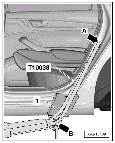
- Secure the vehicle to the hoist lifting arms -arrow B- with the Tensioning Strap -T10038- over the striker pin -arrow A-.
- Place a piece of foam rubber -1- between the sill panel and the Tensioning Strap -T10038- and then tension the Tensioning Strap -T10038-.
Note
Be careful not to scratch the sill panel.
 Caution
The vehicle could fall off the hoist if it is not secured.
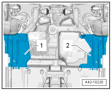
- Remove the underbody covers -1 and 2-. Refer to → Body Exterior; Rep. Gr.66; Underbody Trim Panel; Underbody Panels, Removing and Installing.
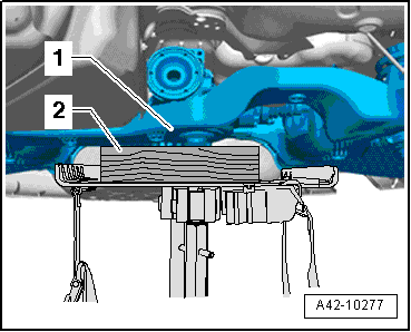
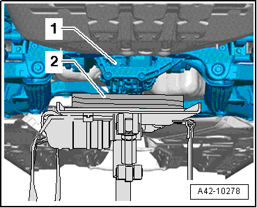
- Place the Engine and Gearbox Jack -VAS6931- under the subframe -1-.
- Place a wood block -2- under the subframe -1-.
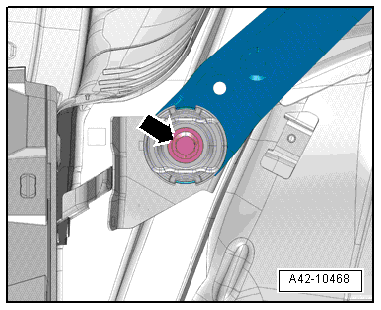
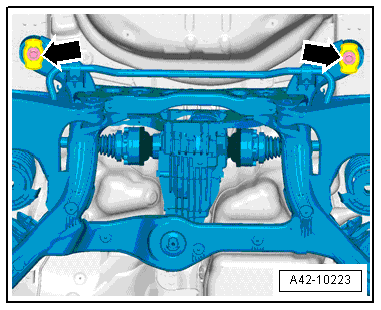
- Remove the left and right bolts -arrow-.
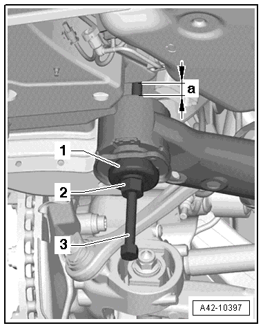
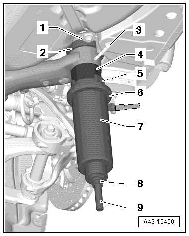
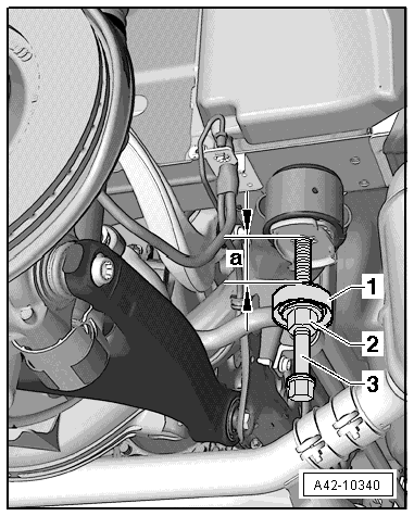
- Install the Subframe Lowering Tool -T40253- with the thrust bearing from the Subframe Bushing Tool Kit -3301- and the Subframe Lowering Tool - Nut -T40253/1-, as illustrated, on the opposite side of the bonded rubber bushing being replaced approximately 1.5 cm into the vehicle body.
1 - Subframe Bushing Tool Kit -3301-
2 - Subframe Lowering Tool - Nut -T40253/1-
3 - Subframe Lowering Tool -T40253-
Note
Turn the Subframe Lowering Tool - Nut -T40253/1- on the Subframe Lowering Tool -T40253- until dimension -a- 4 cm is reached.
- Lower the subframe 4 cm only.
Applies to A Hydraulic Bonded Rubber Bushing
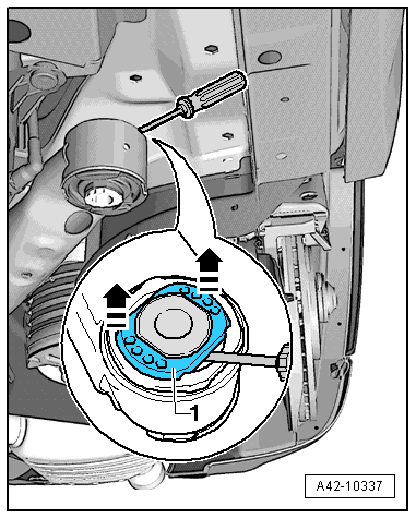
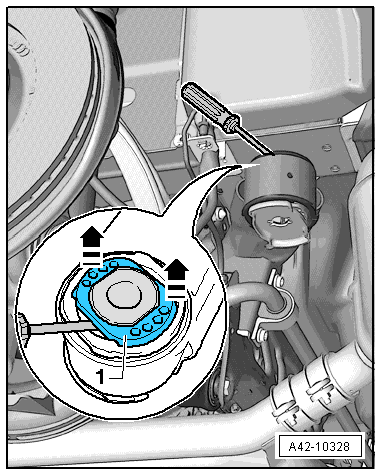
- Remove the plastic stop -1- upward in direction of -arrow- as illustrated.
Applies to All
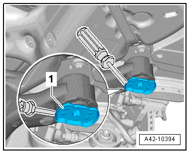
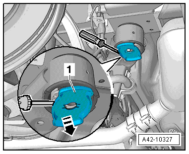
- Pry the stop plate -1- off the bonded rubber bushing alternating from side to side.
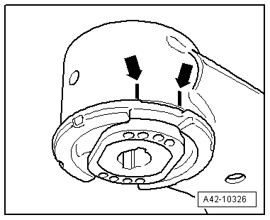
- Mark the installation position of the bonded rubber bushing or the hydraulic bonded rubber bushing on the subframe -arrows- for later installation.
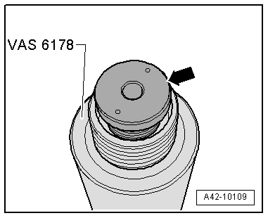
- If necessary, the support -arrow- with the "small" interior diameter must be removed from the Hydraulic Press -VAS6178- and the Pressure Head -T10205/13- for it must be installed.
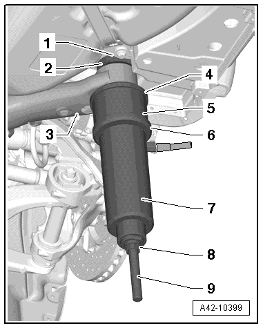
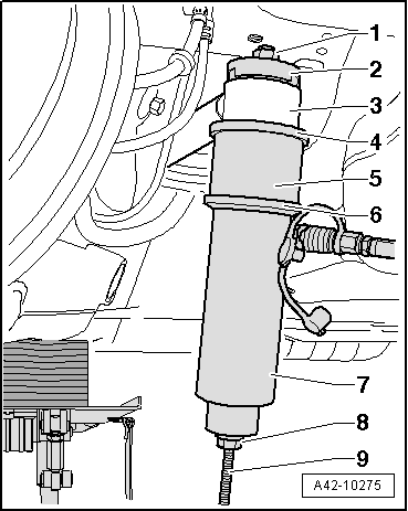
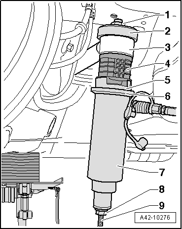
- Place the tools on the front bonded rubber bushing as shown in the illustration.
1 - Hydraulic Press - Rear Subframe Bushing Tool Kit-Nut -T10263/5-
2 - Subframe Bushing Assembly Tool - Thrust Piece -T40185/5-. The opening faces the rubber bonded bushing.
3 - Subframe
4 - Subframe Bushing Assembly Tool - Support Ring - T40185/6-. The conical side must face upward and the ribs must fit into the openings in the rubber bonded bushing.
5 - Rear Bushing Tool - Tube -T40033/3-
6 - Bearing Installer - Wheel Hub/Bearing Kit - 4 -T10205/4-
7 - Hydraulic Press -VAS6178-
8 - Hydraulic Press - Rear Subframe Bushing Tool Kit-Nut -T10263/5-
9 - Hydraulic Press - Rear Subframe Bushing Tool Kit-Spindle -T10263/4- The spindle pins face downward.
 WARNING
- Hold the Hydraulic Press -VAS6178- firmly while pressing out.
- Bonded rubber bushing loosens "abruptly". There is the risk of injuries by tools and bonded rubber bushing coming off!
Installing
- Pry the stop plate -1- near the tabs -arrows- off the bonded rubber bushing alternating from side to side before installing the bonded rubber bushing.
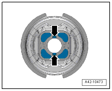
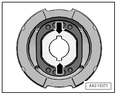
Conventional bonded rubber bushing installed position:
- The grooves -arrows- point in direction of travel.
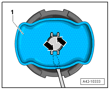
Hydraulic bonded rubber bushing installed position:
- The grooves -arrows- point in direction of travel.
- Place the tools on the front bonded rubber bushing as shown in the illustration.
1 - Hydraulic Press - Rear Subframe Bushing Tool Kit-Nut -T10263/5-
2 - Thrust Piece -T40185/4-
3 - Subframe
4 - Bonded rubber bushing
5 - Subframe Bushing Assembly Tool - Thrust Piece -T40185/3-
6 - Bearing Installer - Wheel Hub/Bearing Kit - 4 -T10205/4-
7 - Hydraulic Press -VAS6178-
8 - Hydraulic Press - Rear Subframe Bushing Tool Kit-Nut -T10263/5-
9 - Hydraulic Press - Rear Subframe Bushing Tool Kit-Spindle -T10263/4- The spindle pins face downward.
- Align the bonded rubber bushing with the markings made previously and push it in until the collar comes in contact with the bushing in the subframe "without any gaps".
Note
- If necessary, tension and press over cylinder several times.
- While pulling in, make sure the bonded rubber bushing does not cant, otherwise outer ring could be damaged.
- The ends of the rubber bead on the bonded rubber bushing must align with the markings -arrows- on the subframe.
Note
After replacing the bearing, fix any paint damage on the subframe with corrosion protection, primer and black top coat.
- Mount the stop plate on the bonded rubber bushing.
Install in reverse order of removal. Note the following:
- Install the diagonal braces. Refer to → Chapter "Diagonal Braces, Removing and Installing".
- Install coil springs. Refer to → Chapter "Spring, Removing and Installing, Coil Spring".
- Install the underbody covers. Refer to → Body Exterior; Rep. Gr.66; Underbody Trim Panel; Overview - Underbody Panels.
- Install rear wheels. Refer to → Chapter "Wheels and Tires".
- Fill the rear axle air springs. Refer to → Chapter "System, Venting or Filling".
Subframe Rear Bearing, Replacing, Vehicles with AWD
Special tools and workshop equipment required
- Subframe Bushing Tool Kit -3301-
- Bearing Installer - Control Arm -3346-
- Torque Wrench 1332 40-200Nm -VAG1332-
- Engine and Gearbox Jack -VAS6931-
- Hydraulic Press -VAS6178-
- Pneumatic/Hydraulic Foot Pump -VAS6179-
- Bearing Installer - Wheel Hub/Bearing Kit -T10205-
- Hydraulic Press - Rear Subframe Bushing Tool Kit -T10263-
- Rear Bushing Tool -T40033-
- Subframe Bushing Assembly Tool -T40185-
Removing
Note
- Check the other bushings before replacing a faulty bonded rubber bushing.
- If cracks, oil leaks or other damage is visible, this bonded rubber busing must be replaced too.
- To replace the rubber bonded bushing, lower the back of the subframe. It is not necessary to remove the subframe.
- Do not lower the subframe more than 4 cm.
- Identify mounting location to subframe before removing the bonded rubber bushing.
- Secure the vehicle to the hoist lifting arms -arrow B- with the Tensioning Strap -T10038- over the striker pin -arrow A-.
- Place a piece of foam rubber -1- between the sill panel and the Tensioning Strap -T10038- and then tension the Tensioning Strap -T10038-.
Note
Be careful not to scratch the sill panel.
Caution
The vehicle could fall off the hoist if it is not secured.
- Remove the rear wheels. Refer to → Chapter "Wheels and Tires".
- Loosen the nuts on rear exhaust system brackets but only as far as to where the thread begins.
- Place the Engine and Gearbox Jack -VAS6931- under the subframe -1-.
- Place a wood block -2- under the subframe -1-.
- Remove the bolts -arrows-.
- Install the Bearing Installer - Component -3346/2- with the thrust bearing from the Subframe Bushing Tool Kit -3301- and Nut - Component -3346/3-, as illustrated, on the opposite side of the bonded rubber bushing being replaced approximately 1.5 cm into the vehicle body.
1 - Subframe Bushing Tool Kit -3301-
2 - Nut - Component -3346/3-
3 - Bearing Installer - Component -3346/2-
Note
Turn the Nut - Component -3346/3- on the Bearing Installer - Component -3346/2- until dimension -a- 4 cm is reached.
- Lower the subframe 4 cm only.
Applies to A Hydraulic Bonded Rubber Bushing
- Pry the plastic stop -1- upward and off the bonded rubber bushing.
Applies to All
- Pry the stop plate -1- off the bonded rubber bushing alternating from side to side.
- Mark the installed position of the hydraulic bonded rubber bushing on the subframe -arrows- with a felt-tip pen for installation later.
- If necessary, the support -arrow- with the "small" interior diameter must be removed from the Hydraulic Press -VAS6178- and the Pressure Head -T10205/13- for it must be installed.
- Place the tools on the front bonded rubber bushing as shown in the illustration.
1 - Hydraulic Press - Rear Subframe Bushing Tool Kit-Nut -T10263/5-
2 - Subframe Bushing Assembly Tool - Thrust Piece -T40185/5-. The opening faces the rubber bonded bushing.
3 - Subframe
4 - Subframe Bushing Assembly Tool - Support Ring -T40185/6-. The conical side must face upward and the ribs must fit into the openings in the rubber bonded bushing.
5 - Rear Bushing Tool - Tube -T40033/3-
6 - Bearing Installer - Wheel Hub/Bearing Kit - 4 -T10205/4-
7 - Hydraulic Press -VAS6178-
8 - Hydraulic Press - Rear Subframe Bushing Tool Kit-Nut -T10263/5-
9 - Hydraulic Press - Rear Subframe Bushing Tool Kit-Spindle -T10263/4- The spindle pins face downward.
WARNING
- Hold the Hydraulic Press -VAS6178- firmly while pressing out.
- Bonded rubber bushing loosens "abruptly". There is the risk of injuries by tools and bonded rubber bushing coming off!
Installing
- Pry the stop plate -1- near the tabs -arrows- off the bonded rubber bushing alternating from side to side before installing the bonded rubber bushing.
Conventional bonded rubber bushing installed position:
- The grooves -arrows- point in direction of travel.
Hydraulic bonded rubber bushing installed position:
- The grooves -arrows- point in direction of travel.
- Place the tools on the rear bonded rubber bushing as shown in the illustration.
1 - Hydraulic Press - Rear Subframe Bushing Tool Kit-Nut -T10263/5-
2 - Thrust Piece -T40185/4-
3 - Subframe
4 - Bonded rubber bushing or the hydraulic bonded rubber bushing
5 - Subframe Bushing Assembly Tool - Thrust Piece -T40185/3-
6 - Bearing Installer - Wheel Hub/Bearing Kit - 4 -T10205/4-
7 - Hydraulic Press -VAS6178-
8 - Hydraulic Press - Rear Subframe Bushing Tool Kit-Nut -T10263/5-
9 - Hydraulic Press - Rear Subframe Bushing Tool Kit-Spindle -T10263/4- The spindle pins face downward.
- Align the bonded rubber bushing with the markings made previously and push it in until the collar comes in contact with the bushing in the subframe "without any gaps". If necessary, tension and press over cylinder several times. While pulling in, make sure the bonded rubber bushing does not cant, otherwise outer ring could be damaged.
- The ends of the rubber bead on the bonded rubber bushing must align with the markings -arrows- on the subframe.
Note
After replacing the bearing, fix any paint damage on the subframe with corrosion protection, primer and black top coat.
- Mount the stop plate on the bonded rubber bushing.
Install in reverse order of removal. Note the following:
- Install the exhaust system bracket. Refer to → Rep. Gr.26; Exhaust Pipes/Mufflers; Overview - Muffler.
- Install rear wheels. Refer to → Chapter "Wheels and Tires".
