Audi A6 Typ 4G: Trailer Hitch
Overview - Trailer Hitch
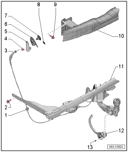
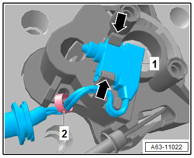
1 - Grommet
- For the cable
2 - Screw
- Tightening specification. Refer to → Chapter "Overview - Impact Member, Audi A6/allroad/S6"
- Quantity: 4
3 - Cable
- For unlocking the trailer hitch
4 - Screw
- 2 Nm
5 - Bracket
- For cable mount
- Removing and installing. Refer to → Chapter "Cable Mount Bracket, Removing and Installing".
6 - Mount
- For the cable
- Removing and installing. Refer to → Chapter "Cable Mount, Removing and Installing".
7 - Pull Knob
- For unlocking the trailer hitch
- Removing and installing. Refer to → Chapter "Cable Mount, Removing and Installing".
8 - Lock Clamp
- For the pull knob
9 - Screw
- Left: 2 washers, right: 4 washers
- Tightening specification. Refer to → Chapter "Overview - Impact Member, Audi A6/allroad/S6"
10 - Impact Member
- For vehicles without a trailer hitch
- Overview. Refer to → Chapter "Overview - Impact Member, Audi A6/allroad/S6".
11 - Impact Member
- For vehicles with a trailer hitch
- Overview. Refer to → Chapter "Overview - Impact Member, Audi A6/allroad/S6".
12 - Socket
- Removing and installing. Refer to → Electrical Equipment General Information; Rep. Gr.96; Trailer Hitch.
- Connector assignment. Refer to → Electrical Equipment General Information; Rep. Gr.96; Trailer Hitch.
13 - Screw
- 3.5 Nm
- Quantity: 3
Cable Mount, Removing and Installing
 WARNING
Danger of causing injury to the legs.
Keep a safe distance from the swivel range of the ball head when unlocking the trailer hitch .
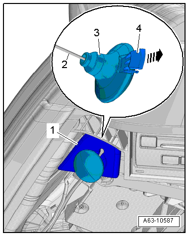
Removing
- Remove the cover from the luggage compartment left trim panel. Refer to → Body Interior; Rep. Gr.70; Luggage Compartment Trim Panels; Luggage Compartment Side Trim Panel, Removing and Installing.
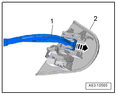
- Remove the pull knob -3- on the mount -1- and pry off the clamp -4- with a narrow screwdriver -arrow-.
- Remove the cable -2- from the pull knob.
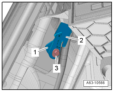
- Remove the cable mount -2- with the cable bracket -1- downward from the bracket -3--arrow-.
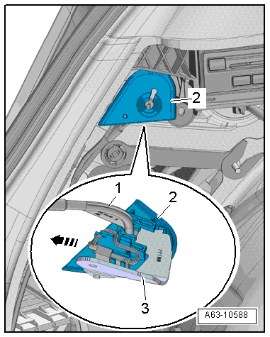
- Disconnect the connector.
- Remove the cable bracket -1- from the mount -2--arrow-.
Installing
Install in reverse order of removal and note the following:
- Install the luggage compartment side trim panel. Refer to → Body Interior; Rep. Gr.70; Luggage Compartment Trim Panels; Luggage Compartment Side Trim Panel, Removing and Installing.
Cable Mount Bracket, Removing and Installing
Removing
- Remove the cable mount -2- with the cable bracket -1- downward from the bracket -3--arrow-.
- Remove the bolt -3- and then remove the bracket -2-.
Installing
- Tightening specification. Refer to → Chapter "Overview - Impact Member, Audi A6/allroad/S6".
Install in reverse order of removal and note the following:
- The lobes -1- on the bracket must engage in the opening on the body.
- Install the cable mount. Refer to → Chapter "Cable Mount, Removing and Installing".
Trailer Hitch, Removing and Installing
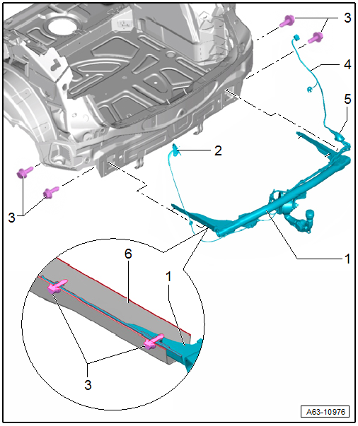
1 - Trailer Hitch
- Removing
- Remove the rear bumper cover. Refer to → Chapter "Bumper Cover, Removing and Installing, Vehicles through MY 2014".
- Pull the control module in the right side panel out of the frame and disconnect the connector.
- Open the cable holder, free up the wiring harness and push outward through the grommet -4-.
- Disengage the cable from the bracket, (Refer to → Chapter "Cable Mount, Removing and Installing".) and remove from the vehicle.
- Remove the bolts -3-.
- Remove the impact member -3- with a second technician.
2 - Cable
- Remove the cable from the mount. Refer to → Chapter "Cable Mount, Removing and Installing".
3 - Screw
- 75 Nm
4 - Wire
5 - Grommet
- Ensure correct seating when installing.
6 - Longitudinal Member
Cable and Trailer Hitch Microswitch, Replacing
 Note
Note
The cable or the microswitch can be replaced individually.
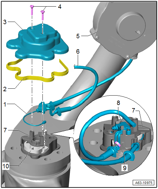
1 - Cable
- Removing
- Remove the trailer hitch.
- Remove the bolts -4- and remove the cover -3- with the seal -2-.
- Guide the cable out the sheave -10- and pull from the bracket. Refer to "Disengage the sheave from the cable".
- Remove the cable transmission. Refer to "Cable Transmission, Removing and Installing".
- Installing
- Install in reverse order of removal.
2 - Seal
- No replacement part, in pushed in the cover
3 - Cover
- Before installing the cable passages must be greased. Refer to "Grease the Cover".
4 - Screw
- 1.5 Nm
5 - Cable Transmission
- Removing and installing. Refer to "Cable Transmission, Removing and Installing".
6 - Wire and Microswitch
- Remove the wire from the connector.
- When installing the wires must be routed down as shown. Refer to "Removing and Installing Micro-switch".
7 - Bracket
8 - Micro-switch
- Removing and Installing.
- Remove the trailer hitch.
 Caution
- When the microswitch is removed the clips can only be carefully bent, there is a risk of damage.
- If the clips are broken the trailer hitch must be replaced.
- Open cable tie -9- and unclip the microswitch -8-.
- Pushed in the bracket as shown.
- When installing pay attention that the wires are counted correctly.
9 - Cable Tie
- After installing secure the wire with a cable tie at the same location.
10 - Sheave
Disengage the Sheave from the Cable
- Disengage the cable -2- with the nipple -arrow- from the sheave -1-.
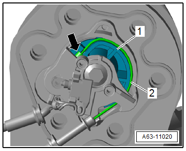
- Remove the cable -1- through the bracket -2-.
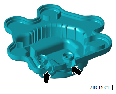
Grease the Cover
- The cable passages -arrows- on the cover must be heavily lubricated with Silicone Grease - G 000 405 A2-.
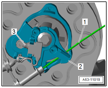
Cable Transmission, Removing and Installing
Removing
- Counterhold with a hex socket wrench on the threaded pin -1-, to remove the nut -2-.
- Remove the bolt -4-.
Installing
- Install the transmission -3- and install the nut -2- hand tight.
- Tighten the screw -4- to 1.5 Nm.
- Counterhold using a hex socket wrench on the threaded pin -1- and tighten the nut -2- to 10 Nm.
Removing and Installing Micro-switch
- Cover removed.
- Remove the wire from the connector.
Caution
- When the microswitch is removed the clips -arrows- can only be carefully bent, there is a risk of damage.
- If the clips are broken the trailer hitch must be replaced.
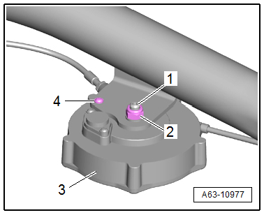
- Remove the cable tie -2- to remove.
- Carefully bend the retaining tabs -arrows- and unclip the microswitch -1- from the mount and remove upward.
- When installing route the wire as shown and secure with a cable tie.
- Push the microswitch in the clamp.
Special Tools
Special tools and workshop equipment required
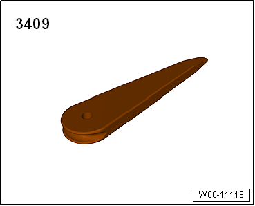
- Trim Removal Wedge -3409-
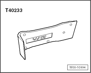
- Removal Wedge -T40233-
- Front and Rear Door Template -T40038 /8-
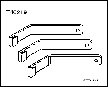
- Window Slot Seal Tool -T40219-
- Double Suction Lifter -VAG1344-
- Wiring Harness Repair Set - Hot Air Blower -VAS 1978/14A-
- Gauge - Gap Adjustment -3371-
- Locking Pliers -VAS6199-
- Transmission Support -VW 785/1 B-
- Protective Gloves
Revision History
DRUCK NUMBER: A005A000221