Audi A6 Typ 4G: Driveshaft, Removing and Installing
Driveshaft, Removing and Installing, Driveshaft Connected on Transmission Side
Special tools and workshop equipment required
- Transmission Support -VW785/1B-
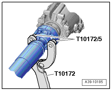
- Counterhold - Kit - Multiple Use -T10172-
- Counterhold - Kit - Adapter 5 -T10172/5-
- Hose Clip Pliers -VAG1275A-
- High Temperature Grease -G 052 133 A3-
Removing
 Note
Note
- The attached driveshaft can only be separated from the transmission if it is completely removed.
- Perform work on driveshaft on a two-column workshop hoist if possible.
- After removing the driveshaft from the rear final drive, tie up the shaft ends or hold them up.
- The driveshaft can be bent all the way to the center joint without force. Bending the joint forcibly all the way can damage the center joint and/or the protective boot.
- Always remove or install the driveshaft horizontally from the transmission output shaft.
 Caution
Risk of damaging the coupling elements.
- Do not bend the coupling more than 10º.
- Do not load the coupling.
- Do not damage the wire mesh on the coupling.
Vehicles with 3.0L TDI driveshaft and Two Turbochargers
- Remove the particulate filter or SCR catalytic converter. Refer to → 6-Cylinder TDI Common Rail 3.0L 4V Engine (Generation II); Rep. Gr.26; Emissions Control; Particulate Filter, Removing and Installing.
Continuation for all Vehicles
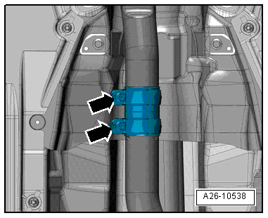
- Loosen clamping sleeve(s) -arrows- and push it toward the rear.
- Tie the front muffler or the left and right front exhaust pipe to the underbody.
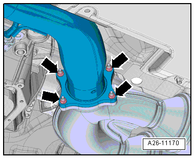
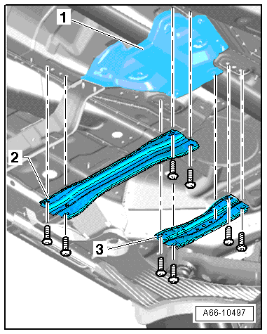
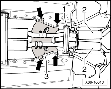
- Remove the bolts -arrows- and remove the driveshaft heat shield -1- (if equipped).

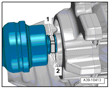
- Cut the clamp -1- for the driveshaft boot and remove it.
Note
Ignore -item 2-.
Audi A6 and A7
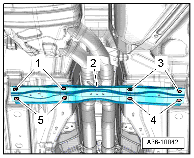
- Remove the crossmember -2-. Refer to → Body Exterior; Rep. Gr.66; Underbody Panel; Overview - Underbody Panels.
Audi A4, A5 Coupe, A5 Sportback, A5 Cabrio, Q5, A8
- If equipped, remove the front crossmember -2- and the rear crossmember -3-. Refer to → Body Exterior; Rep. Gr.66; Underbody Panel; Overview - Underbody Panels.
Continuation for all Vehicles
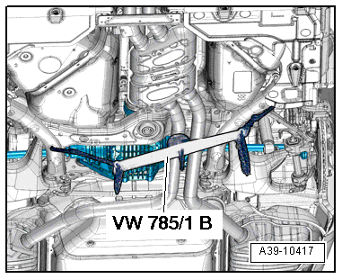
- Remove the heat shield -1-.
- Lower the front of the exhaust system rear section and then secure it using the Transmission Support -VW 785/1 B-, as illustrated.
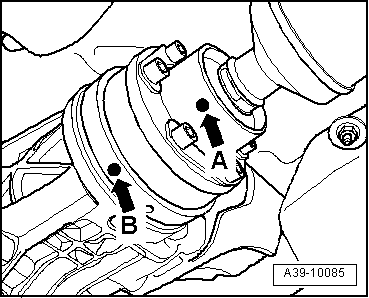
- Make sure there is a mark (color dot) on the driveshaft and on the rear final drive driveshaft flange -arrow A and arrow B-.
- Make a color dot again if the original mark is no longer visible.
- The dots on the driveshaft -arrow A- and on the rear final drive -arrow B- must line up.
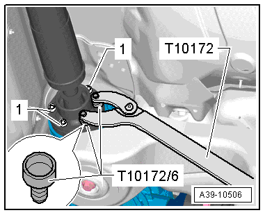
- Remove the driveshaft bolts -1- from the rear final drive.
- Counterhold with Counterhold - Kit - Multiple Use -T10172- and Counterhold - Kit - Adapter 5 -T10172/5-.
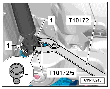
- Use the Counterhold - Kit - Multiple Use - Adapter 6 -T10172/6- for the rear final drive 0BE.
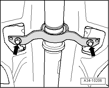
- Remove the bolts -arrows- for the driveshaft intermediate bearing.
- Bend the driveshaft on the intermediate bearing all the way without force.
Note
- The driveshaft can be bent slightly further in some positions.
- Turn the driveshaft slightly.
- Guide the rear driveshaft on the fuel tank and on the rear subframe downward and remove it from the transmission.
Installing
- Tightening specifications. Refer to → Chapter "Overview - Driveshaft, Mounted On Transmission Side" and → Fig. "Driveshaft Heat Shield - Tightening Specification".
Note
- Remove any old, dry high-temperature grease from the CV joint and the driveshaft flange. Fill with the exact same amount of new High Temperature Grease.
- The threads in the flange shaft on the rear final drive must be cleaned of locking fluid residue. They can be cleaned with a thread tap. If the threads are not clean, the bolts will break off when they are being installed.
- Replace the self-locking driveshaft bolts.
- Replace the hose clamps -1- for the driveshaft boot -2-.
- Check the driveshaft seal on the rear final drive flange for damage (bent, rubber layer worn off) and replace if damaged. Replace the damaged seal.
- Wipe the splines on the transmission output shaft with a towel before installing the driveshaft. The splines are not lubricated.
- First mount the driveshaft on the transmission.
- Maximum bend angle: 10º.
- After the driveshaft is inserted approximately 50 mm into the transmission output shaft, turn the driveshaft slightly to make sure that the transmission output shaft splines are meshed into the inner splines of the driveshaft.
- Push the driveshaft all the way onto the splines on the transmission output shaft.
- Bend the driveshaft on the intermediate bearing all the way without force.
Note
- The driveshaft can be bent slightly further in some positions.
- Turn the driveshaft slightly.
- Guide the rear driveshaft on the subframe and fuel tank upward.
- Install the bolts -arrows- just far enough so that the so the intermediate bearing can still be moved.
- Position the driveshaft on the rear final drive while paying attention to the installation position:
- The dots on the driveshaft -arrow A- and on the rear final drive -arrow B- must line up.
- Maximum difference between the markings: 30º.
- Install the new bolts all the way in by hand but do not tighten them.
- Line up the hose clamp -1- for the driveshaft boot with the retainers -2- and then tighten the clamp using for example the Hose Clamp Pliers -VAG1275A-.
Note
In order to use the Hose Clamp Pliers -VAG1275A- correctly, move the driveshaft a little toward the rear.
- Tighten the driveshaft bolts -1-. Follow the tightening sequence. Refer to → Fig. "Driveshaft to Rear Final Drive - Tightening Specification and Sequence".
- Tighten the driveshaft intermediate bearing on the body without tension. Tightening specification. Refer to -item 9-.
Install in reverse order of removal. Note the following:
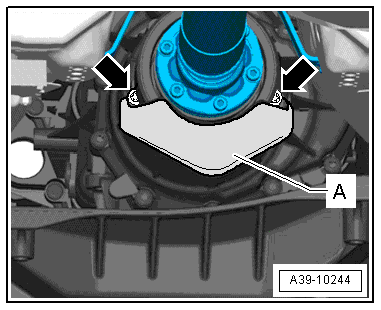
- Tighten the heat shield -A- to the transmission -arrows-. Tightening specification. Refer to → Fig. "Driveshaft Heat Shield - Tightening Specification".
- Install the heat shield -1-. Refer to → Body Exterior; Rep. Gr.66; Underbody Trim Panel; Overview - Underbody Trim Panel.
- If equipped, install the front crossmember -2- and the rear crossmember -3-. Refer to → Body Exterior; Rep. Gr.66; Underbody Trim Panel; Overview - Underbody Trim Panel.
Vehicles with 3.0L TDI Engine and Two Turbochargers.
- Install the particulate filter or SCR catalytic converter. Refer to → 6-Cylinder TDI Common Rail 3.0L 4V Engine; Rep. Gr.26; Emissions Control System; Particulate Filter, Removing and Installing.
- Install the exhaust system and align it without tension. Refer to → Rep. Gr.26; Exhaust Pipes/Muffler; Overview - Muffler.
Driveshaft, Removing and Installing, Driveshaft Bolted on Transmission Side
Special tools and workshop equipment required
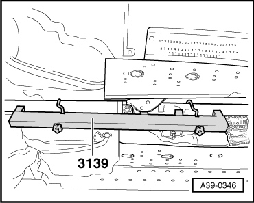
- Drive Axle Alignment Fixture - 3139-
- Counterhold - Kit - Multiple Use -T10172- with Counterhold - Kit - Adapter 5 - T10172/5-
- Engine and Gearbox Jack -VAS6931- with Universal Transmission Support -VAG1359/2-
- High Temperature Grease. Refer to the Parts Catalog.
Driveshaft, Removing
- Note the instructions. Refer to → Chapter "Overview - Driveshaft, Bolts On Transmission Side".
- A two-column workshop hoist should be used when working on the driveshaft.
Note
Do not bend the flex joint in the front exhaust pipe more than 10º or it will be damaged.
- Loosen the clamping sleeve(s) -arrows- and separate the exhaust system.
- Tie the front exhaust pipe(s) to the underbody.
- Remove the rear section of the exhaust system -2-. Refer to → Rep. Gr.26; Exhaust Pipes/Mufflers; Overview - Muffler.
Note
A second technician is needed to help remove the rear section of the exhaust system.
Audi A4 and Audi A5
- Remove the crossmember -1-.
- Remove the heat shield -3--arrows-.
Audi Q5
- Remove the front -2- and rear -3- crossmembers.
- Remove the heat shield -1-.
Continuation for all Vehicles
- Remove the heat shield -A- from the transmission -arrows-, if applicable.
- Check whether there is a color dot on the driveshaft and at flange/driveshaft on the rear final drive -arrow A and arrow B-
- If one of these markings is no longer visible (for example -arrow A- on the driveshaft), then mark the missing point in color.
- The mark on the driveshaft -arrow A- and on the rear final drive -arrow B- are on one line.
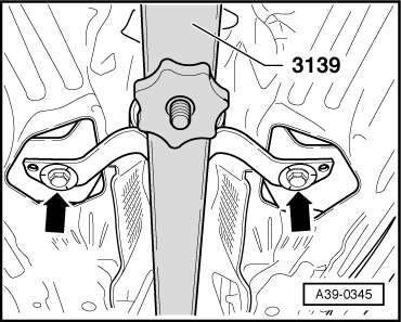
- Attach the Drive Axle Alignment Fixture -3139- and tighten the plastic nuts.
Note
Never place the Alignment Fixture on the balance plates.
- Remove the intermediate bearing bolts -arrows-.
- Remove the bolts attaching the driveshaft to the transmission by counterholding with the Counterhold - Multiple Use -T10172A- and with the Counterhold - Kit - Adapter 5 -T10172/5- or Counterhold - Kit - Adapter 6 -T10172/6-.
- Remove the driveshaft from the transmission and support the driveshaft with the Engine and Gearbox Jack -VAS6931-.
- Remove the bolts -1- (quantity: 6) from the rear CV joint.
- Use the Counterhold - Kit - Multiple Use -T10172- with Counterhold - Kit - Adapter 5 -T10172/5- or Counterhold - Kit - Adapter 6 -T10172/6-.
- Remove the driveshaft.
Note
Always transport and store driveshaft when it is fully extended.
Driveshaft, Installing
Install in reverse order of removal. Note the following:
- Remove the old, dry High Temperature Grease from the CV joints and the driveshaft flanges. Fill with the exact same amount of new High Temperature Grease.
- Always remove any remaining locking fluid from thread bores in drive flanges for transmission driveshaft and for rear final drive. They can be cleaned with a thread tap. If the threads are not clean, the bolts will break off when they are being installed.
- After removing the driveshaft from the rear final drive, do not install the additional balance washer (thicker washer) that may be between the backing plate and the bolt.
- Always replace the bolts for driveshaft (self-locking bolts).
- Pay attention to the installed position of the driveshaft: the center of the CV joint is located behind the intermediate bearing facing the rear final drive.
- Check the driveshaft seal on the rear final drive flange and the transmission for damage (bent, rubber layer worn off) and replace if damaged. Replace the damaged seal.
- Install the driveshaft while paying attention to the rear final drive:
- The dots on the driveshaft -arrow A- and on the rear final drive -arrow B- must line up.
- Maximum difference between the markings: 30º.
- Install the new bolts all the way in by hand but do not tighten them.
- Install the bolts -arrows- just far enough so that the so the intermediate bearing can still be moved.
- Tighten the bolts -1- on the rear driveshaft. Follow the tightening sequence. Refer to → Fig. "Driveshaft to Rear Final Drive - Tightening Specification and Sequence".
- Tighten the bolts on the front driveshaft. Tightening specification. Refer to -item 5-.
- Remove the Drive Axle Alignment Fixture -3139-.
- Tighten the driveshaft intermediate bearing on the body without tension. Tightening specification. Refer to -item 8-.
- Tighten the heat shield -A- to the transmission -arrows-. Tightening Specification. Refer to → Fig. "Driveshaft Heat Shield - Tightening Specification".
- Install the heat shield -1-.
- If equipped, install the front crossmember -2- and the rear crossmember -3-. Refer to → Body Exterior; Rep. Gr.66; Underbody Panel; Overview - Underbody Panels.
- Install the exhaust system and align it without tension. Refer to → Rep. Gr.26; Exhaust Pipes/Mufflers; Overview - Muffler.
