Audi A6 Typ 4G: Mechatronic
Overview - Mechatronic
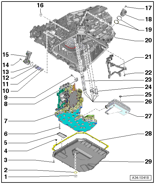
1 - ATF Drain Plug
- Tightening specification -item 1-.
2 - Seal
- Replacing
3 - Bolt
- Tightening specification and sequence, refer to → S tronic Transmission Internal Components; Rep. Gr.34; Mechatronic; Overview - Mechatronic.
4 - Clip
- For attaching the gasket to the ATF oil pan
- Not required for installation
5 - Magnet
- Quantity: 2
- insert into the depression in the ATF oil pan
- Make sure the entire surface contacts oil pan
6 - Bolt
- Tightening specification and sequence, refer to → S tronic Transmission Internal Components; Rep. Gr.34; Mechatronic; Overview - Mechatronic.
7 - S tronic Transmission Mechatronic -J743-
- After replacing the S tronic Transmission Mechatronic -J743-, the corresponding "Guided Functions" must be performed with the Vehicle Diagnostic Tester, refer to → Chapter "Transmission Guided Functions".
- Disconnecting the S tronic Transmission Mechatronic - J743- circuit board, refer to → S tronic Transmission Internal Components; Rep. Gr.34; Mechatronic.
8 - Retaining Plate
- for the ATF oil pipes
9 - Bolt
- Tightening specification and sequence, refer to → S tronic Transmission Internal Components; Rep. Gr.34; Mechatronic; Overview - Mechatronic.
10 - O-Rings
- Are replaced together with the ATF pipe (-item 11-)
- Coat with ATF before installing
11 - ATF Pipes
- Replacing
12 - O-Rings
- Are replaced together with the ATF pipe (-item 9-)
- Coat with ATF before installing
13 - O-Ring
- Replacing
- Coat with ATF before installing
14 - Bolt
- Tightening specification -item 12-.
15 - For the Replaceable ATF Filter Housing
- Removing and installing, refer to → Chapter "ATF Filter Housing, Removing and Installing".
- Different versions depending on the date of manufacture, pat attention to the correct allocation.
16 - ATF Fill and Check Plug
- Tightening specification -item 4-.
17 - Bolt
- Tightening specification and sequence, refer to → S tronic Transmission Internal Components; Rep. Gr.34; Mechatronic; Overview - Mechatronic.
18 - Connector Housing
- Remove the screw -item 17- and turn the connection housing counter-clockwise.
19 - O-Rings
- Replacing
20 - Transmission Housing
21 - Wiring Harness
22 - Bolt
- Tightening specification and sequence, refer to → S tronic Transmission Internal Components; Rep. Gr.34; Mechatronic; Overview - Mechatronic.
23 - ATF Pipes
24 - ATF Pipes
- Different versions depending on the date of manufacture, one or three pieces
25 - O-Ring
- Replacing
26 - O-Rings
- Replacing
27 - ATF Suction Filter
- Removing and Installing, refer to → S tronic Transmission Internal Components; Rep. Gr.34; Mechatronic.
28 - Seal
- Replacing
- Installing
29 - ATF Pan
- Refer to → Chapter "Oil Pan, Removing and Installing"
Oil Pan, Removing and Installing
Removing
 Note
Note
- General Repair Instructions, refer to → Chapter "General Repair Information".
- Rules for cleanliness when working on the S tronic transmission, refer to → Chapter "Guidelines for Clean Working Conditions".
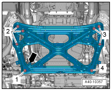
- Remove the subframe crossbrace, refer to → Suspension, Wheels, Steering; Rep. Gr.40; Subframe; Subframe Crossbrace, Removing and Installing.
 Caution
The suspension components could be damaged.
Do not rest the vehicle on its wheels if the subframe mount, the steering gear or the subframe crossbrace are not installed correctly.
- Drain the ATF, refer to → Chapter "ATF, Draining and Filling".
 Caution
Danger of causing damage to the transmission.
Do not start the engine when there is no ATF in the transmission.
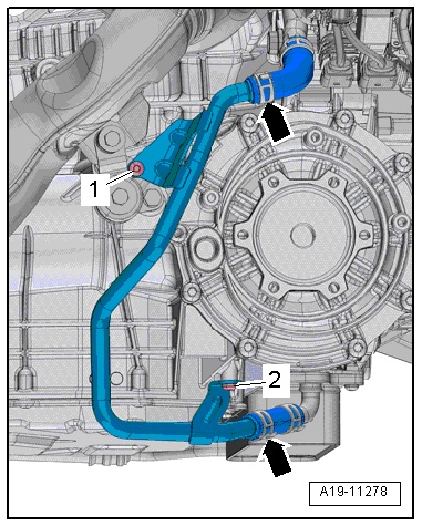
Vehicles with a 8-cylinder gasoline engine:
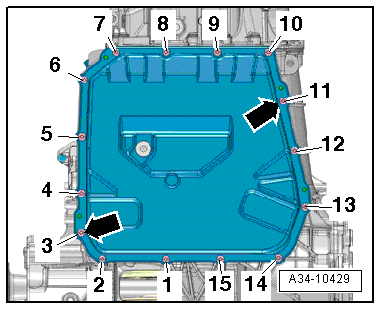
- Remove the bolts -1, 2- and then press the coolant pipe on the right to the side.
 Note
Note
Ignore -item 3- and -arrows-.
All vehicles:
- Diagonally Loosen the screws -1 through 15-.
- Remove the bolts and the ATF pan.
 Note
Note
Ignore -arrows-.
Installing
Install in reverse order of removal. Note the following:
- Clean the sealing surfaces.
- Replace the ATF oil pan bolts and gasket.
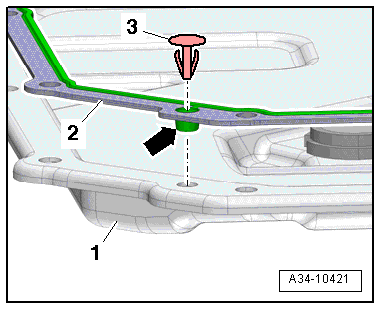
- Insert the guides -arrow- on the new gasket -2- into the ATF fluid pan -1-.
- Attach the gasket and clips -3- to the ATF pan.
 Note
Note
Clips -item 3- are only used for assembly help during production!
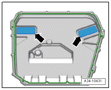
- Clean the magnets -arrows- in the ATF pan.
- Make sure the magnets completely contact the depressions in the ATF oil pan.
- Tighten the ATF pan bolts, refer to → S tronic Transmission Internal Components; Rep. Gr.34; Mechatronic; Overview - Mechatronic.
- Install the right coolant pipe on the transmission, refer to → Rep. Gr.19; Coolant Pipes; Coolant Pipes, Removing and Installing.
- Fill the ATF, refer to → Chapter "ATF Level, Checking".
Tightening Specifications
- Subframe crossbrace, refer to → Suspension, Wheels, Steering; Rep. Gr.40; Subframe; Overview - Subframe.

Mechatronic, Removing and Installing
Special tools and workshop equipment required
- Used Oil Collection and Extraction Unit -SMN372500-
Removing
- The transmission is installed.
 Caution
Danger of causing damage to the transmission.
Do not start the engine if there is no ATF in the transmission or if the S tronic transmission Mechatronic -J743- is removed.
 Note
Note
- General Repair Instructions, refer to → Chapter "General Repair Information".
- Rules for cleanliness when working on the S tronic transmission, refer to → Chapter "Guidelines for Clean Working Conditions".
- S tronic Transmission 0B5 Information, refer to → Chapter "General Information".
- Move the selector lever into "P".
- Turn off the ignition and remove the key.
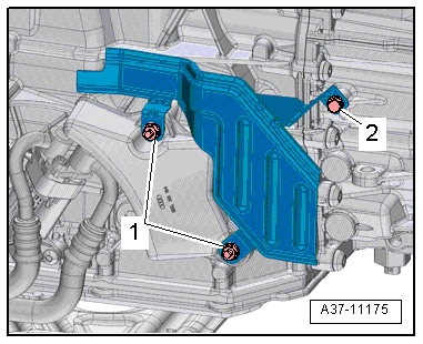
- Remove the nuts -1- and the bolt -2- and then remove the heat shield.
 Caution
There is a risk of destroying the transmission control module (Mechatronic) with static discharge.
- Always "discharge" the static electricity before working with electric connectors. Do this by touching a grounded object, for example vehicle ground, the vehicle or the hoist.
- Do not touch contacts in transmission connector with hands.
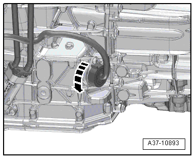
- Turn the twist lock counter-clockwise -arrow- and disconnect the connector from the transmission.
- Remove the ATF filter housing, refer to → Chapter "ATF Filter Housing, Removing and Installing".
Description of additional procedures, refer to → S tronic Transmission Internal Components; Rep. Gr.34; Mechatronic; Mechatronic, Removing and Installing.
Installing
Install in reverse order of removal. Note the following:
 Caution
There is a risk of destroying the transmission control module (Mechatronic) with static discharge.
- Always "discharge" the static electricity before working with electric connectors. Do this by touching a grounded object, for example vehicle ground, the vehicle or the hoist.
- Do not touch contacts in transmission connector with hands.
- Make sure the connector is correctly connected to the Mechatronic.
- Install the ATF filter housing, refer to → Chapter "ATF Filter Housing, Removing and Installing".
- Install the ATF pan, refer to → Chapter "Oil Pan, Removing and Installing".
- Fill the ATF, refer to → Chapter "ATF Level, Checking".
- After replacing the S tronic Transmission Mechatronic -J743-, the corresponding "Guided Functions" must be performed with the Vehicle Diagnostic Tester, refer to → Chapter "Transmission Guided Functions".
