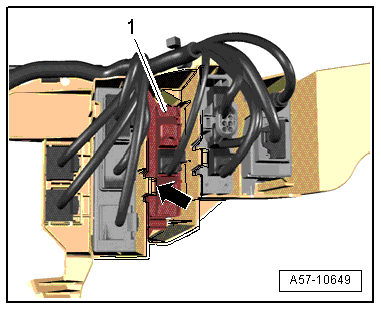
Audi A6 Typ 4G: Vehicle Positioning System Interface Control Module -J843-, Removing and Installing
Removing
- Open the cover in the luggage compartment right trim panel.
- Disconnect the control module connectors -1-.
- Release the tab -arrow- and remove the control module.
Installing
Install in reverse order of removal.
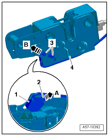
Engine Hood Contact Switch -F266-, Removing and Installing
Removing
- Remove the hood latch. Refer to → Chapter "Overview - Hood, Hood Latch".
- Raise the retaining tab -2--arrow A-.
- Disengage the hood switch -F266--item 1- from the lock -4--arrow B- and remove it.
Installing
Install in reverse order of removal. Note the following:
- The centering pins -3- on the engine Hood Contact Switch -F266- must fit correctly inside the hood lock.
Fuel Filler Door Unlock Motor -V155-, Removing and Installing
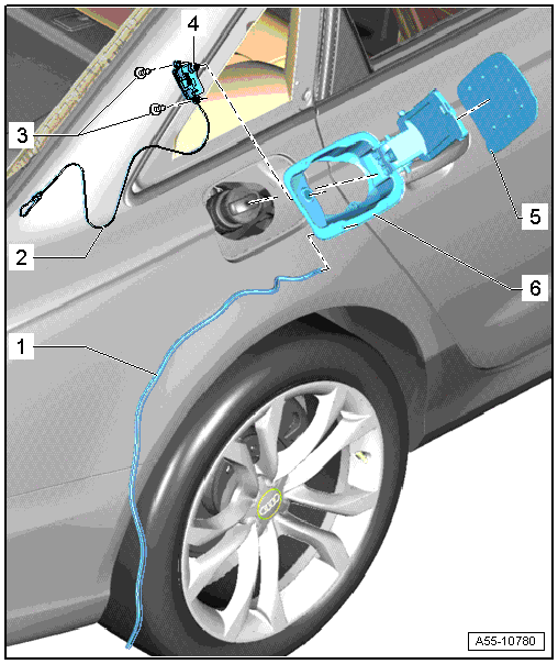
1 - Drain Hose
- Routing
2 - Emergency Release Cable
- Routing
3 - Bolt
- 1.5 Nm
4 - Fuel Filler Door Unlock Motor -V155-
- Removing
- The fuel filler door is removed. Refer to → Chapter "Fuel Filler Door Unit, Removing and Installing".
- Remove the bolt -3- on the Fuel Filler Door Unlock Motor -V155-.
- Disconnect the connector and remove the Fuel Filler Door Unlock Motor -V155-.
- Installing
- Connect the fuel filler door to the Fuel Filler Door Unlock Motor -V155- with the bolt -3-.
- Push the drain hose and emergency release cable through the cut-out in the side panel.
- Install the fuel filler door with the Fuel Filler Door Unlock -V155- at an angle in the tank opening and push in until the retaining tabs on the flange engage.
- pay attention that the drain hose.
5 - Fuel Filler Door Cover
- Removing and installing. Refer to → Chapter "Fuel Filler Door Cover, Removing and Installing".
6 - Fuel Filler Door Unit
- Must be replaced after removing
- Removing. Refer to → Chapter "Fuel Filler Door Unit, Removing and Installing"
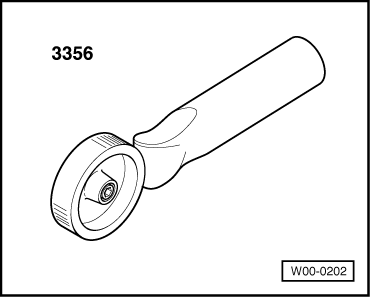
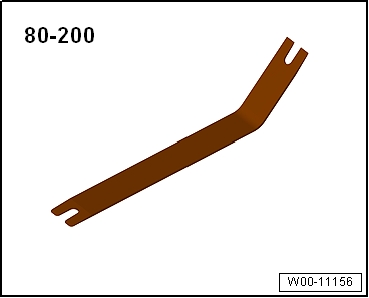
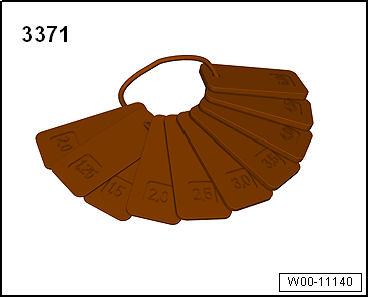
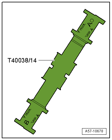
Special Tools
Special tools and workshop equipment required
- Roller -3356-
- Pry Lever -80 - 200-
- Front and Rear Door Template -T40038/8-
- Gauge - Gap Adjustment -3371-
- Front and Rear Door Template -T40038 /14-
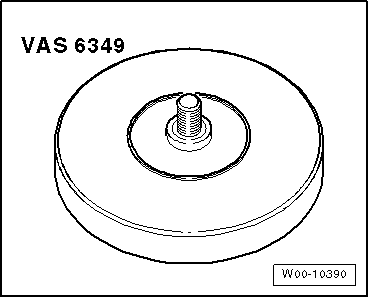
- Adhesive Strip Remover -VAS6349-