Audi A6 Typ 4G: Wheel Covers, Removing and Installing
Fender Molding, Replacing
Special tools and workshop equipment required
- Roller -3356-
- Gauge - Gap Adjustment -3371-
- Front and Rear Door Template -T40038 /8-
 Note
Note
- The attached trim can only be replaced, removal without destruction is not possible.
- Remove adhesive residue on body if necessary.
- Clean the adhesive surfaces on the vehicle body with Cleaning Solution -D 009 401 04-.
- Adhesion surfaces must be free of dust and grease
- Heat the adhesive surface and trim to approximately 40º C (104 ºF) before bonding
- When installing, the trim must be applied according to the contours. It is not possible to make corrections later.
- Press the covers with the Roller -3356- after installation.
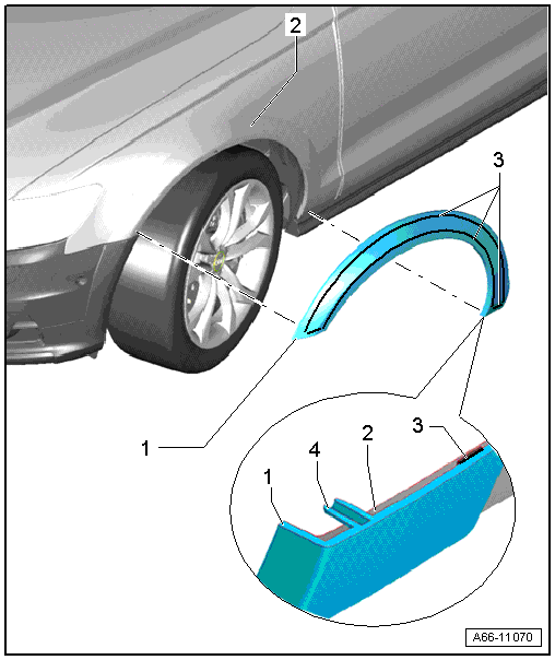
1 - Wheel Cover
- Removing:
- Warm the adhesive surface with a hot air gun and pull off the cover little by little.
- Remove any remaining adhesive on the side panel, if necessary.
- Installing:
- Remove the protective film sideways so that they can be reached when the fender cover is dismantled.
- Position it above the centering pin from rear to front and in line with the contour when installing.
- Pull off the protective backing at the removal tabs between the side panel and molding and then press the molding on using Roller -3356-.
2 - Fender
3 - Adhesive Tape
- Before installing, bend the protective backing 90º so it can be reached when the protective molding is installed on the fender.
4 - Centering Pin
Wheel Cover for Side Panel and Rear Door, Replacing
Special tools and workshop equipment required
- Roller -3356-
- Gauge - Gap Adjustment -3371-
- Front and Rear Door Template -T40038 /8-
Note
- The attached trim must be replaced, removal without destruction is not possible.
- Remove adhesive residue on body if necessary.
- Clean the adhesive surfaces on the vehicle body with Cleaning Solution -D 009 401 04-.
- Adhesion surfaces must be free of dust and grease
- Heat the adhesive surface and trim to approximately 40º C (104 ºF) before bonding
- When installing, the trim must be applied according to the contours. It is not possible to make corrections later.
- Press the covers with the Roller -3356- after installation.
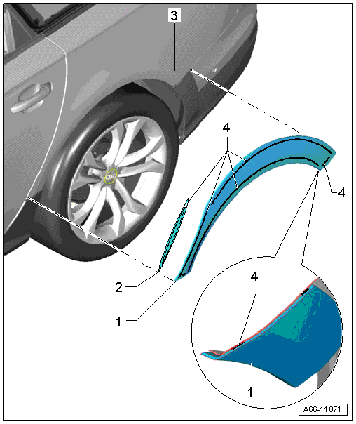
1 - Side Panel Fender Molding
- Removing:
- Warm the adhesive surface with a hot air gun and pull off the cover little by little.
- Installing:
- Remove the protective film sideways so that they can be reached when the side panel cover is dismantled.
- Position it exactly along the contour on the sill panel trim and door trim
- Remove the protective film by the removal tabs between the side panel and trim and press it on by hand in stages.
2 - Rear Door Trim
- Removing and installing is identical to removing and installing the fender molding.
3 - Side Panel
4 - Adhesive Tape
- Before installing, bend the protective backing 90º so it can be reached when the protective molding is installed on the fender.
