Audi A6 Typ 4G: Windshield
Overview - Windshield
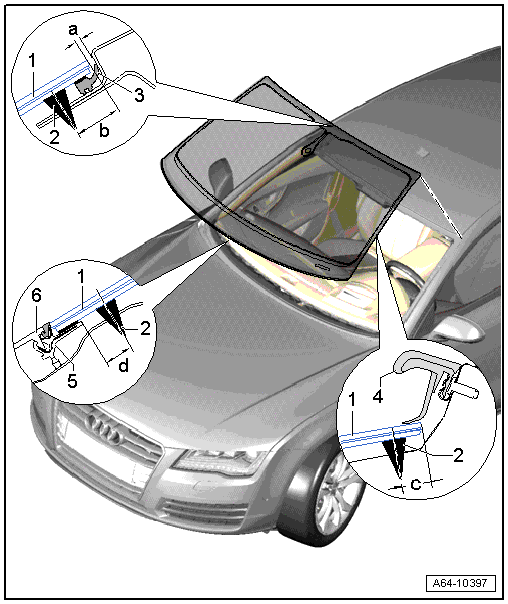
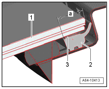
1 - Windshield
- Distance to the roof, dimension -a- = 2 mm
- Center the side distance to the A-pillars.
2 - Adhesive Bead
- Observe the minimum curing time. Refer to → Chapter "Minimum Curing Time for Bonded Windows".
- Dimension -b- = 17 mm +- 2 mm
- Dimension -c- = 10 mm +- 2 mm
- Dimension -d- = 8 mm +- 2 mm
3 - Gap Cover
- Replacing
4 - Drip Rail
5 - Plenum Chamber Cover Frame
- No replacement part
- With a new window, protective piping must first be removed before installing plenum chamber cover.
6 - Plenum Chamber Cover
- Press into retaining strip only after window adhesive minimum curing time is complete (3 hours).
Allocation of the Windshield to the Driver Assistance Systems Front Camera -R242-.
Before ordering a new windshield on vehicle version with a Driver Assistance Systems Front Camera -R242- the version must be determined.
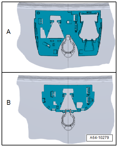
- Retaining plate for the Driver Assistance Systems Front Camera -R242- older version ⇒ windshield older version allocation
- Retaining plate for the Driver Assistance Systems Front Camera -R242- newer version ⇒ windshield newer version allocation
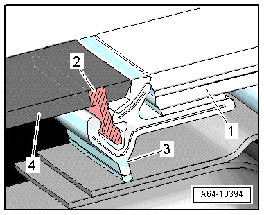
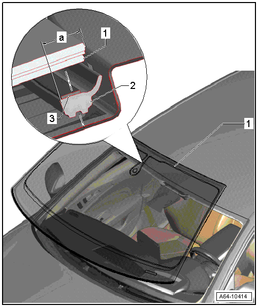
Protective Piping, Removing
- With a new windshield -1-, protective piping -2- must be removed from molding -3- before installing plenum chamber cover -4-.
Windshield, Removing and Installing
Windshield, Removing and Installing
 Caution
- On vehicles equipped with lane assist, the camera must be recalibrated if the windshield has been replaced. Refer to → Suspension, Wheels, Steering; Rep. Gr.44; Driver Assistance Systems Front Camera; Driver Assistance Systems Front Camera, Calibrating.
- The Windshield Projection Head Up Display Control Module -J898- must be calibrated if the windshield on a vehicle with windshield projection is replaced. Refer to → Electrical Equipment; Rep. Gr.90; Instrument Cluster; Windshield Projection Head Up Display Control Module, Calibrating.
- Remove the windshield wiper arms. Refer to → Electrical Equipment; Rep. Gr.92; Windshield Wiper System; Windshield Wiper Arms, Removing and Installing.
- Remove cowl panel trim. Refer to → Chapter "Cowl, Removing and Installing".
- Remove the left center and right sun visor. Refer to → Body Interior; Rep. Gr.68; Equipment; Overview - Sun Visors.
- Remove the interior rearview mirror. Refer to → Body Interior; Rep. Gr.68; Interior Rearview Mirror; Interior Rearview Mirror, Removing and Installing.
- Remove the left and right upper A-pillar trim panels. Refer to → Body Interior; Rep. Gr.70; Passenger Compartment Trim; A-Pillar Trim Panel, Removing and Installing.
 WARNING
When removing a window, always wear protective eyewear and leather gloves.
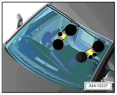
- Unroll with the Cutting Tool for Bonded Windows - Wire Reel -VAS 6452/1- approximately 6.5 meters of cutting wire (approximately six turns) and cut it.
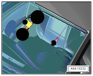
- Cover the awl outlet under the body flange with tape -1- to prevent damaging it.
- Poke the awl through the bead of adhesive from the inside to the outside as illustrated.
- Feed both cutting wire ends -3- into the awl -2- and pull it in.
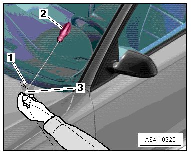
- Place the cutting wire all the way around under the windshield as illustrated.
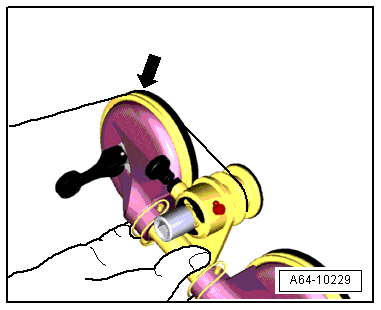
Caution
The ends of the wire must not be twisted when cutting through the adhesive -arrow-.
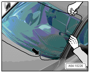
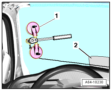
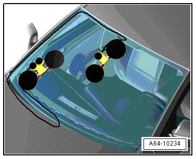
- Mount both reel devices on the inside of the windshield as illustrated.
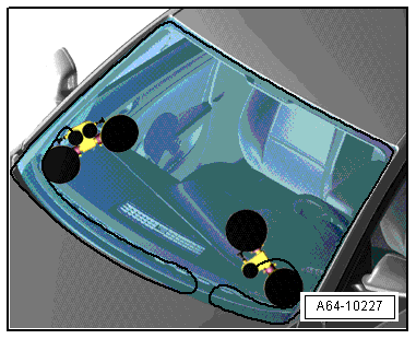
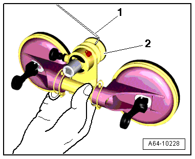
- Insert the ends of the cutting wire -1- into the reel device -2-
- Tension the cutting wire and place the protective foil -2- between the instrument panel and the wire
- Cut the first section open, while doing this, the wire is guided into the integrated roller -arrow- on the reel device.
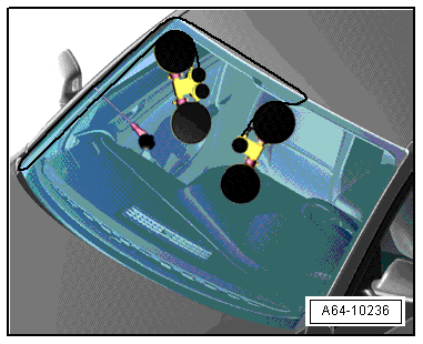
- Insert an additional guide awl -2- into the adhesive and secure it to the windshield with the suction cup as illustrated to make sure that the wire runs as close to the windshield as possible.
- If necessary, move the protective film -3- along with the wire and cut the windshield free with the reel device -1-.
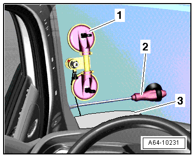
- Move the reel device and the guide awl as illustrated and cut free the section along the "A-pillar".
- Moved the reel device and guide awl approximately to the center of the windshield.
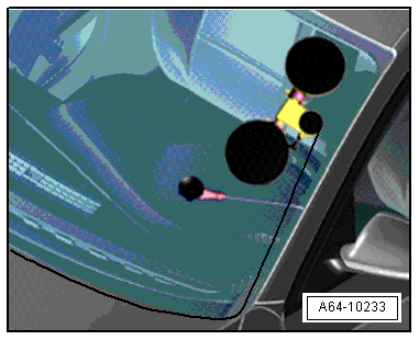
- Cut free the windshield up to about the center.
- Cut free the bottom of the windshield with the second reel device.
- Move the reel device upward and insert the guide awl as illustrated.
- Cut the windshield free moving upward along the "A-pillar".
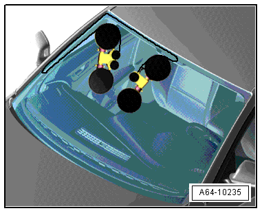
- Move the reel device over the center of the windshield and over the first reel device as illustrated and cut free the rest of the windshield along the top.
- Remove the windshield from the vehicle with the suction cups.
Installing
- Installing. Refer to → Chapter "Bonded Window Glass Installation Instructions".
- Prepare the undamaged window for installing. Refer to → Chapter "Undamaged Window Glass, Preparing for Installation".
- Prepare the new window for installation. Refer to → Chapter "New Window Glass, Preparing for Installation".
- Prepare the body flange for installation. Refer to → Chapter "Body Flange, Preparing for Installation".
- Using suction cups, install the windshield.
Caution
The window must be installed within 15 minutes or the adhesive sealing material will not adhere properly.
- Center window along sides.
- Distance from the window edge to the roof frame. Refer to -item 1-.
- Secure the window to the top of the roof with adhesive tape.
- Before installing the cowl panel trim, first remove protective profile -2- from the frame.
- Observe the minimum curing time. Refer to → Chapter "Minimum Curing Time for Bonded Windows".
Gap Cover, Replacing
1 - Windshield
- Removed
2 - Gap Cover
- Adhering.
- Before installing new gap cover, remove residue completely using a commercially available window scraper to avoid damaging ceramic screen printed area.
- Clean adhesion area with cleaning solution D 009 401 04.
- Apply a mark on the window interior using, for example, a soft pencil at a distance -a- = 8 mm from upper window edge.
- Prime adhesion surface with D 009 200 02 up to marking applied earlier and let it air dry for at least 10 minutes.
- Press the gap cover onto the glass starting in the middle with the rear edge facing the primer end (pencil marking).
- Reinstall window.
Installing the Gap Cover
- Windshield -1- with ceramic coating.
- Clean adhesion area with cleaning solution D 009 041 04.
- Now apply a marking at uniform distance -a- = 8 mm to top of window edge.
- Apply glass/paint primer D 009 200 02 cleanly up to marking.
- Let the glass/paint primer air out for at least 10 minutes.
- Remove the protective foil from double-sided adhesive tape -3-.
- Place the gap cover -2- in the center and onto the window glass with the rear edge facing the primed end (marking).
- Press profile firmly onto window using a roller.